Adding a 220 Outlet
I have a large induction motor that is rated for about 19 amps at 110, and about 9.5 at 220. My 15 amp table saw motor also has a tendency to trip the breaker when it first starts, depending on what else is running on the same circuit. The best fix, if possible, is simply switching everything over to 220V power and adding a 220 outlet if one isn’t already available.
At 220 volts (also referred to as 230 or 240), the amperage for a given device is halved. This means that you can safely run thinner gauge wire, which is cheaper. The increased amperage also helps an induction motor spin up faster. Certain machines that require a lot of power, such as really big bandsaws and large welders, can only be run on 220. This makes it handy to have available in any shop. Contrary to popular belief, switching from 110 to 220 does not increase the power available in a typical motor.
Disclaimer: I am not an electrician. Doing my own work is legal where I live, but it may be illegal where you live. This writeup is documenting what I did for entertainment purposes. It is not a course or instruction manual. You should consult a professional before doing ANY electric work on your house.
Required Supplies
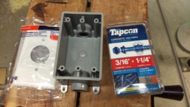
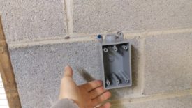
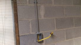
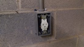
There are a few items required to install a new 220 outlet, all of which are readily available at the Home Depot or any similar store. My outlet was going into my basement shop, which already had exposed conduit and outlet boxes screwed directly into cinderblock. In other words, it is not framed. As a result, I simply needed an outlet box, as pictured, plus a 220 outlet cover and some 1-1/4″ Tapcon concrete screws
.
I also had to get some conduit to run between the outlet box and the ceiling. This stuff is extremely cheap at any home store. You could also use the galvanized boxes and conduit, but plastic seems easier to work with and less likely to conduct.
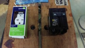
Also required is a 220 outlet and 220 circuit breaker
. These need to be sized for the required load. In my case, I knew my loads would be 7-10 amps. Breakers this small for 220 aren’t very common, so I went ahead and sized up to 20 amps. There’s a slight danger in going too big, in that a breaker may not trip when it needs to, but this amount of oversizing shouldn’t cause any problems.
There are multiple styles of 220 outlet, but the linked 6-20R is a very common plug type for woodworking equipment. It shouldn’t matter which you use as long as you’re consistent, unless your equipment also requires 110V power. (This is much more common with kitchen appliances than tools.) Also be aware that different outlets are rated for different maximum power. Be sure to get one large enough. There are also multiple styles of circuit breaker, so I had to be sure to match the same type as what was already in the breaker box.
Note that I did not get a Ground Fault Circuit Interrupter (GFCI) outlet. For a 110 circuit, I would absolutely do this, but the same concept doesn’t carry over to 220. Details are outside the scope of this article.
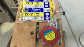
The last thing I needed was wire. This needs to be sized to the breaker and outlet as well. For 20 amps, 12 gauge wiring is appropriate.
Wiring Choices
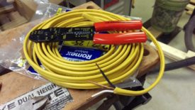
I’ll just add a note here about Romex wiring. As I said, I chose 12 gauge to match my 20 amp circuit. For 30 amps, I’d move up to a 10 gauge wire. For a 110 outlet, it’s enough to simply buy standard 12-2 Romex, which has a hot (black), a neutral (white), and a ground wire (unsheathed). For 220, you have two hots and a ground. You can get 12-3 wire
, which is a bit more expensive, but has two hots (one black, one red), a ground (unsheathed), and a neutral (white). You need 12-3 for the aforementioned case where you have an appliance requiring both 220 and 110 volts. For tools, as I said, this generally does not apply.
I chose to cheap out and get 12-2. It’s roughly 2/3 the price. In my area, this is perfectly find and up to code as long as you mark the white wire with red. You can do this with liquid tape, red electrical tape, or my choice, red heat shrink. The point here is that an electrician will treat the white wire as neutral and therefore safe. If you’re running 220 and using that white wire as a hot instead, you need to mark it red so that the next guy doesn’t make a stupid mistake.
Mounting the Outlet Box
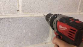
The first step in the process is to mount the outlet box to hold the outlet. When using Tapcon concrete anchors, it’s best to get as many of the screws in the mortar as possible, as it provides a better hold. Tapcon includes an appropriately-sized pilot hole drill bit with their larger screw packs.
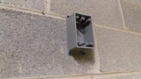
Once the pilot hole is drilled, the PVC box can be mounted using that one screw location. The other 3 pilot holes can now be drilled through the box, to ensure they’re located properly. Lastly, all 4 screws can be put in.
Adding the Outlet
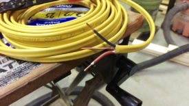
The next step is to wire up an outlet into the box. To start, I stripped the end of the wire I bought and added red heatshrink to the white wire to make it clear to the next guy that this is a hot, not a neutral. If you read the next step, I kind of wish I had waited to do this.
I’m going to describe what I should have done, rather than did. The easiest approach is to cut the conduit to size. You can use a hacksaw, miter saw
, or oscillating multitool
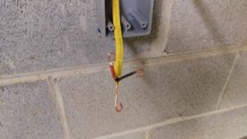
else for this purpose. Pull the un-stripped wire through the cut down conduit, and then through the top of the box. Let the conduit dangle. Now, go strip the wire, apply the red heat shrink, and curl the ends to attach to the box. Trying to push the stripped wire through the conduit was pretty annoying.
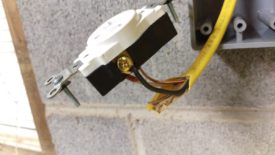
For a standard 100V outlet, you’d want to make sure not to mix the hot and neutral up. In this case, I have two hots, so it doesn’t matter which is which. The important thing is that the unshielded ground attaches to the green screw, and the two hots attach to the other two.
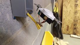
After that, I was able to pull the wiring back until only a few inches were left. (I pulled it farther than pictured.) At that point, I could simply push the outlet into the box and screw it down.
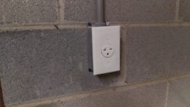
Finally, I got the cover put on, completing the installation of the box. It should now be firmly mounted in place.
Running the Wire
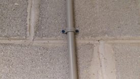
The next step was to secure the conduit to the wall. I had about a 3′ span of conduit, so I only needed a couple of anchors. These attach in much the same way as the outlet box. I simply sunk them in with a couple of Tapcons.
At this point, the outlet box is done, and completely secured to the wall. I now just have to run the wire along the joists on the ceiling to the breaker panel.
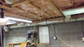
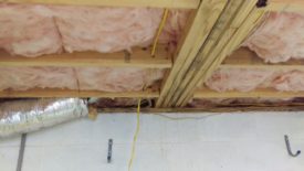
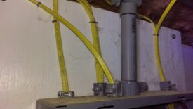
Since my basement shop is not framed up or finished, it was really easy to run the wiring. I simply followed what the original builders had done and used large staples to secure the wire along the joist. To go through the joists towards the wall, I drilled a hole as pictured. Once I reached the far wall, I again followed the staple method to get to the breaker box. I didn’t get a great picture of the staples, but the pictured dangling wire was pulled tight near the ceiling.
For a finished basement, this would have required a lot less stapling, but a lot more fishing of wire with fish rods, fish tape
, or something similar. To be honest, I hate doing that kind of job and would probably hire somebody.
Adding More Outlets
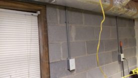
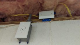
It’s worth noting that further outlets can be added, as well. In fact, I did just that, adding this second outlet on the way to the breaker box. The basic procedure is the same, except that both outlets tie into the junction box at the top right. The electric code in most areas does not allow wire nut connections to sit out in the open, for obvious reasons. They must be in a junction box.
I could get an oversized outlet box and jam extra connections into it. Instead, I simply put in a second junction box. Wires from both outlets, as well as the breaker box, run to this junction box. They are all connected together with wire nuts and enclosed safely inside to avoid fire risk.
Add the Circuit to the Breaker Box
Up until this point, everything has been essentially safe. I’m dealing with exposed walls, so I’m not in danger of drilling into any hidden live wires. Nothing is actually connected to electricity yet. Here’s where things get dangerous, so again, Do not blindly follow what I’m doing without consulting a professional. You could get injured opening up your breaker box. It may also be illegal depending on your area.
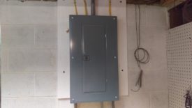
Now that I had wire brought all the way to the box, it was time to install the circuit. My shop already has its own sub-panel, so that is where my circuit was going. It is important to make sure not to overload the panel, but in my case, I had very few circuits anyway. I turned off the master power on this panel, as well as turning it off from the main breaker. I wanted to be sure the panel was totally cold, and then I treated it as though it were still live anyway.
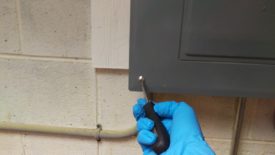
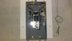
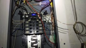
With everything shut off, I removed the six screws holding the cover on. Here you can see the exposed panel. For the uninitiated, what we have is the large main hot line running down the middle through a 100amp master fuse, which is of course shut off. The individual circuit breakers plug in, and the hot lead for each circuit connects to the screw on its breaker. Just to the left and right of the breaker are banks of connectors for the neutral wire. These shouldn’t carry power unless someone mis-wired the box. (Which does happen!) Lastly, on the right, the ground wires all connect to a final bank. This should never carry electricity, and if it does a ground fault has occurred, which can be very dangerous.
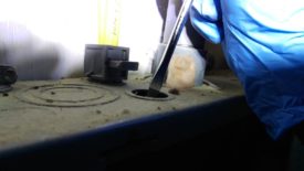
I needed to run my Romex into the box itself. I punched out one of these break-out connectors with a screwdriver.
The wire is run through, with one of these clamp on things holding it to the breaker box.
On the inside of the box, I stripped all the wire back to where it comes into the breaker. I put heatshrink on the white wire all the way up, as well, to make sure anyone examining the box would know it is a hot wire.
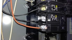
Then, I plugged in the new circuit breaker I had bought. It depends slightly on what kind of breakers you have, but they usually lock in one side and then push in on the other. 220V breakers have two screw connections, instead of the typical one on a 110V breaker. I connected the black hot to one, and the red hot to the other.
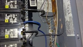
The last step for wiring was to attach the ground wire to the bank on the right.
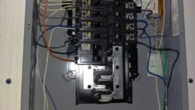
Before I could reattach the panel cover, I needed to remove two of the blanks for my new circuit breaker. I just twisted them off with a pair of pliers.
Wrap-up and Testing
Once that was done, with the circuit breaker still off, I put the panel cover back on and labelled the circuit in the list on the door. Finally, I held my breath and flipped the breakers back on. Mostly kidding, I knew it would work.
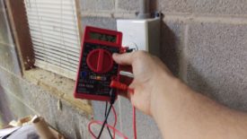
As a last step before actually hooking up a machine, I used a voltmeter set to high-voltage AC mode to confirm everything was solid. As you can see, with both leads connected to my two hot wires, I have 252 volts. The expected range is 220 to 240 volts. So what is going on, did I screw up??
Well, actually, no. Unexpectedly high voltage can indicate that there’s an issue with your wiring, but after panicking, I went back across my house with the voltmeter and noticed that the voltage was consistently high everywhere. The 110 outlets were at about 132, and the 220 outlets, including the ones for my dryer and stove, were at about 250 as well. This said to me the problem could actually be the transformer on the street.
Sure enough, before I even had a chance to call the power company, they were actually doing work on the transformer nearest to me. The next day, I saw that my 110 outlets had dropped to about 118, and the 240 outlets were all closer to 236. This is still a little bit high, but within allowed tolerance, so I let it go.



Consumers had bumped up the voltage in Bronson, MI to 508 volts. The reason was to be able to provide more power to the industrial park without replacing the 12 miles of power line from the high tension line.
Romex shouldn’t be run through conduit
It should when run along a wall to an outlet in a space that isn’t going to be finished. You don’t just string bare romex down a wall and leave it exposed. 😉
If this were through framing and going to be behind drywall, I would agree with you.
Thanks for the comment.
My understanding is that Romex still should not be run in a conduit as it can lead to excess heat build up. Insulated wire such as THHN and THWN would be appropriate for this type of an application, however.
conduit on exposed, visible, unprotected walls.
What really throws a monkeywrench in it for me is that Romex is made of THHN wires. So to be “more compliant” could you strip the sheathing back on the section of the run that will be going thru conduit?
I don’t know. I matched the wiring (romex through conduit) that the licensed electrician who initially wired the shop ran, and thus assumed it was correct / code for my area. YMMV.
Wire encased in Romex sheathing and then encased in a conduit can overheat. You want to use straight THHN wire inside conduits, not Romex.
Hi all, ran across this article when searching for dual phase (220v) devices working “out of the box” in Europe since I have a couple of devices like this (requiring 220v in the US) and want to take them with me on a long term assignment… Is it just a case of switching the plug to a European plug since they are already 220v over there? Tx.
Unfortunately it isn’t that simple. While they’re both 220, US power is 220 at 60hz, whereas European power is generally 50hz, and of course the plugs are different. I don’t think European power will have a 110 leg accessible the way a lot of US plugs, like dryer plugs, will either?
Granted, most things will be 50/60hz compatible. The ideal thing would be if whatever you’re trying to move with you has a supported power cord from the manufacturer intended for Europe.