Miata Coolant Reroute (M-Tuned)
The problem with the Miata cooling system
While I had the engine out, per the removal instructions in another article, I decided to also do a coolant reroute. For those not aware, the Miata 1.8L engine is shared with the Ford Escort and some other Mazda compact cars. Being initially designed for a front wheel drive car, it was designed for transverse mounting. This means the crank is situated to the side of the engine, so it can hook up to a transmission over the front wheels.
In the miata, it had to be mounted longitudinally, meaning the crank is towards the back of the engine bay. The transmission is in the middle of the car in the hump between the passenger and driver seats. There is no problem with this, except for cooling flow. The cooling was designed to come into the engine from one side of the engine bay and go out the other, flowing through the block and head. However, when they rotated the engine, this meant coolant would flow from front to back.
The issue with this is that it put the thermostat at the back of the engine, sandwiched between the engine and the firewall. The thermostat needs to be able to be periodically replaced, so this presented a problem. What they decided to do was route the coolant so it went into the bottom front of the engine, all the way to the back, and then to the front again out the top front. So on a Miata, the coolant inlet and outlet are both on the front. The issue with this is that the 4th cylinder, all the way at the back, gets cooked. When I had my radiator burst at a track day, the spark plug on the 4th cylinder was the most burnt.
The Miata coolant reroute, such as the M-Tuned reroute, locates the thermostat back to the back of the engine and restores the intended coolant flow. This cools all of the cylinders more evenly and prevents this situation from happening. The net effect is that, although the thermostat is slightly less convenient to get to, coolant flows properly through the engine.
A note about 01-04 engines
In the VVT NB motors, from 2001 to 2004, Mazda changed the headgasket. The coolant flow to the front cylinders is restricted to force more coolant towards the back and attempt to ameliorate the flow problem. It does mostly work, albeit not as well as a reroute.
If you have an 01-04 motor, you must put on an earlier year head gasket

any of the other 1.8L headgaskets (94-00)
Pre-installation work
Anyway, enough theory, and on to the installation. I did this while the engine was on a stand, which is by far the easiest. However, it can definitely be done with the engine in the car, as m-tuned’s own instructions show. Doing it on the stand enabled me to get more clear pictures on the installation process.
Before continuing, you should drain the coolant into a suitable container and dispose of it properly. You can look at the relevant section in my engine removal article if you’re not sure how to do this. You will also need to disconnect the heater core hose that goes into the rear water fitting cover.
There is only one, it is the one that goes to the back of the engine as opposed to the driver’s side. It’s located higher and on the cover with the coolant sensor. You do not have to disconnect the from the heater core (the side against the firewall), which is usually more difficult anyway. If you can’t remove them, you may have to cut them off and replace.
Removing the rear water fitting cover
Getting into this area with the engine in the car is going to be a big pain, but it can be done. As I said, these shots were taken with my engine on a stand. If you’re needing to do an engine swap or otherwise have the engine removed, it does make the install much easier.
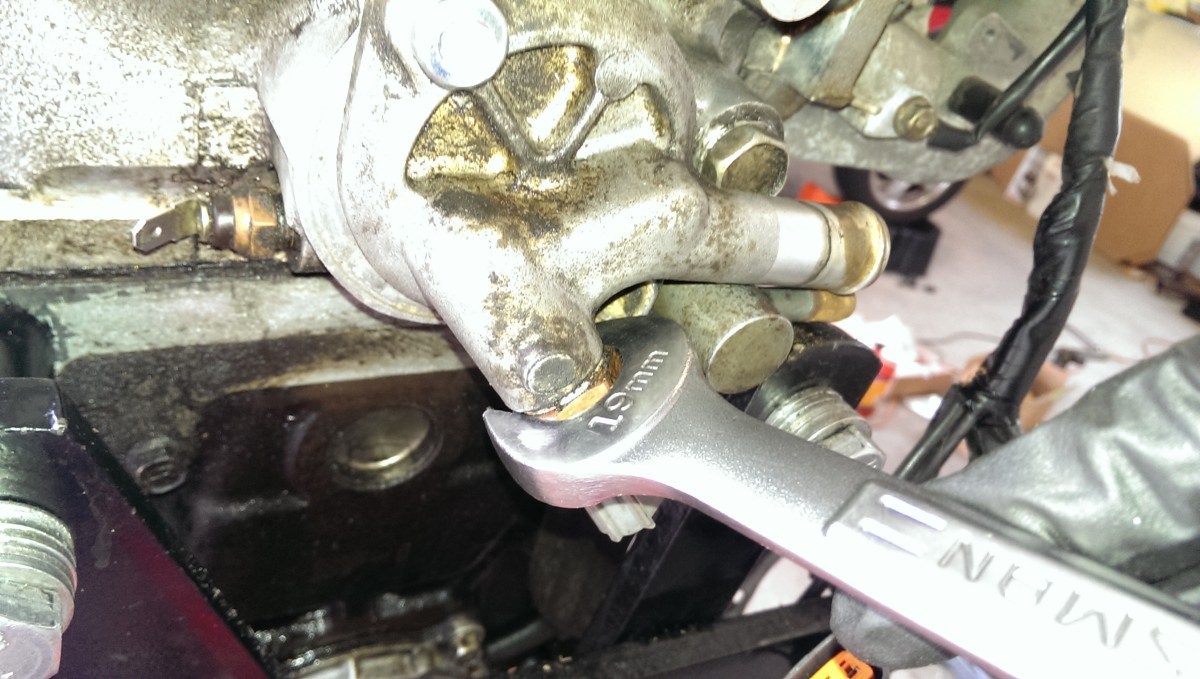
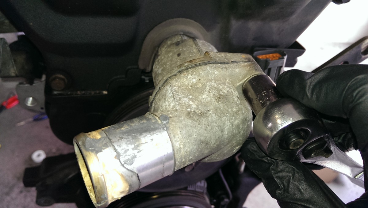
Remove the temperature sensor first
The first thing you want to do at the back of the engine is remove your coolant temperature sensor. It can simply be undone with a wrench. Note that this picture actually shows the rear water fitting cover, or whatever this thing is called, installed backwards. I removed it, then realized I couldn’t get the sensor loose without it being held in place by the engine, and slapped it back on really quick the wrong way around. Use your imagination, it’s the only sensor in the area with a big electronic plug sticking into it. If for some reason you can’t get to the plug very easily, you could remove the cover and put it in a bench vise or something to hold it while you unbolt the sensor.
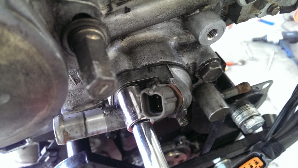
Unbolt the cover
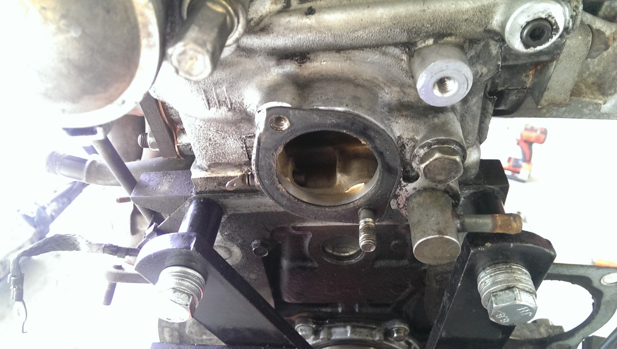
Remove the gasket; note the remaining stud
With the sensor out, remove the two nuts holding the cover on. As noted above, pretend the sensor is off already in this picture – you it is much easier to remove it with the cover still held by the engine. Note that these are not bolts, they are actually studs with a nut on them. In my case, one of the nuts came off the stud. In the other case, they were corroded together enough that the stud and nut came out as though it were one bolt. For the new reroute part, you’re not going to reuse these anyway, so the studs need to come out.
Also scrape the old gasket off. It should be made as clean as possible, although I don’t bother to clean the surface all that carefully because I use liberal amounts of RTV anyway, and I haven’t had any leaks. Still, it’s a good idea to remove all the paper and as much gunk as possible without scratching it.
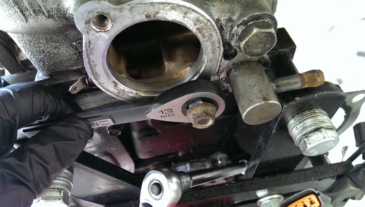
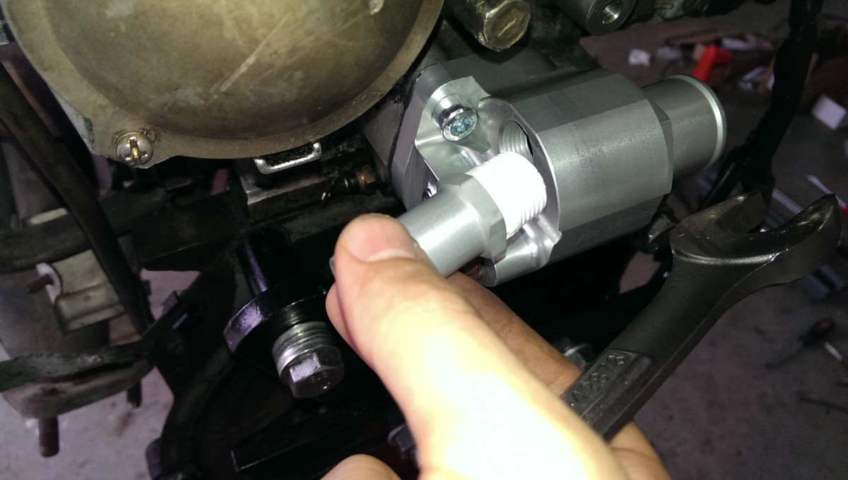
Use two nuts, with the wrench on the inner one, to back the stud out
If one of them doesn’t come free, like in my picture, you can use the double nut trick to remove it. Simply thread two nuts onto the stud, and turn the wrench on the innermost one as pictured. The inner nut will spin off but be held by the outer one, and the stud will turn.
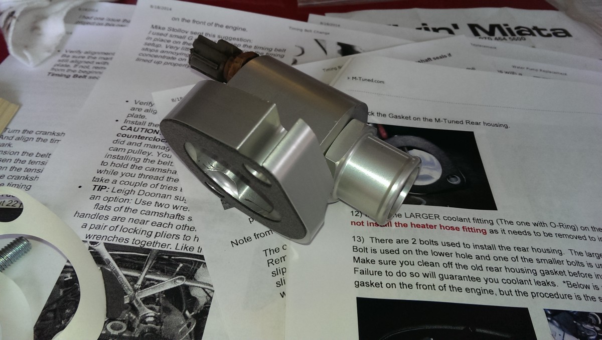
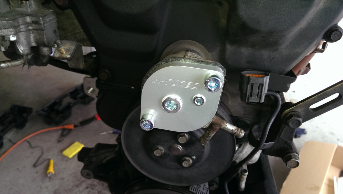
Installing the new rear water opening cover
This piece is what makes the whole kit work. Instead of the previous water fitting, which only housed the heater core line and the temperature sensor, this one also has an outlet to push coolant back around to the radiator, through a thermostat.
Note about thread sealant
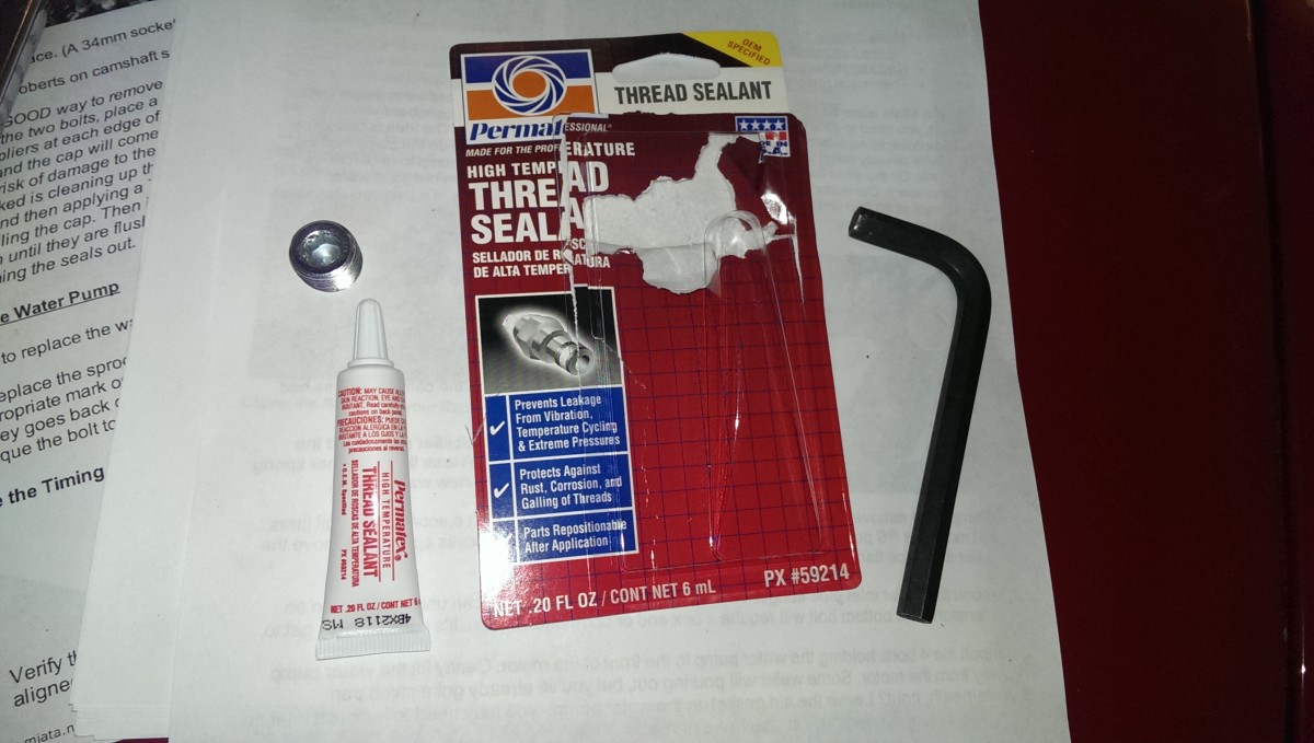
This stuff works way better than thread tape
M-tuned recommends using teflon tape around the connections to seal them against leaks. This is the same stuff you’d use in your house for your plumbing lines. I initially began to use this, and then searching on miataturbo.net I discovered some people were instead using thread sealant
Moral of the story: use thread sealant, not thread tape, on all of the water connections for this install.
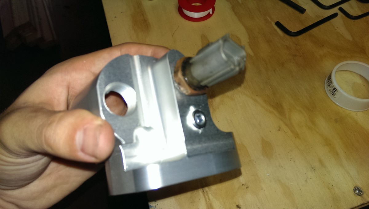
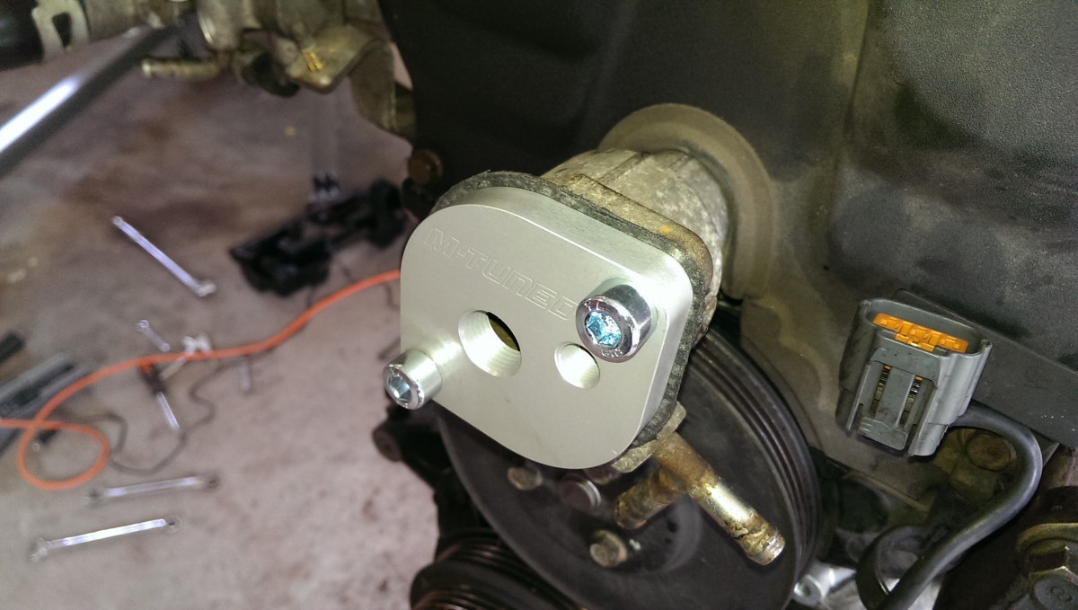
Use pipe sealant (not tape as pictured) and install plugs in the rear cover
There is thread tape on it in the picture, but I went back and used thread sealant instead. Go ahead and install the plugs on the cover that came with the kit. These ports are to allow you to tap the cooling lines for various reasons, be it a turbo, aftermarket gauges, or whatever. I was using none of the above, so I simply installed them.
Install the heater core fitting BEFORE the cover if you’re doing this with engine in car
Also note that the fitting for the heater core hose also needs to be installed. I did that with the cover on the engine a few pictures down, but if you’re doing this with the engine in the car, you may want to do it prior to installation. This picture shows the cover already installed because I did it in a different order, but I’m putting this here so people don’t struggle to get the cover on and then find out that this fitting is missing.
Add the provided stick-on gasket
M-tuned provides a stick-on gasket. If you’re doing this with the engine in the car, this is probably a godsend – it won’t flop around while you’re trying to install. I also used a probably-excessive amount of Ultra Black RTV on the engine side before installation. This isn’t strictly necessary, but I didn’t want to have any leaks. The cover side is fresh, clean, unscratched metal, so I wasn’t as concerned as with the engine mating surface.
Also note that the coolant sensor needs to be installed on the new cover. If the engine is in the car, like everything else, it’s probably easier to do before installation.
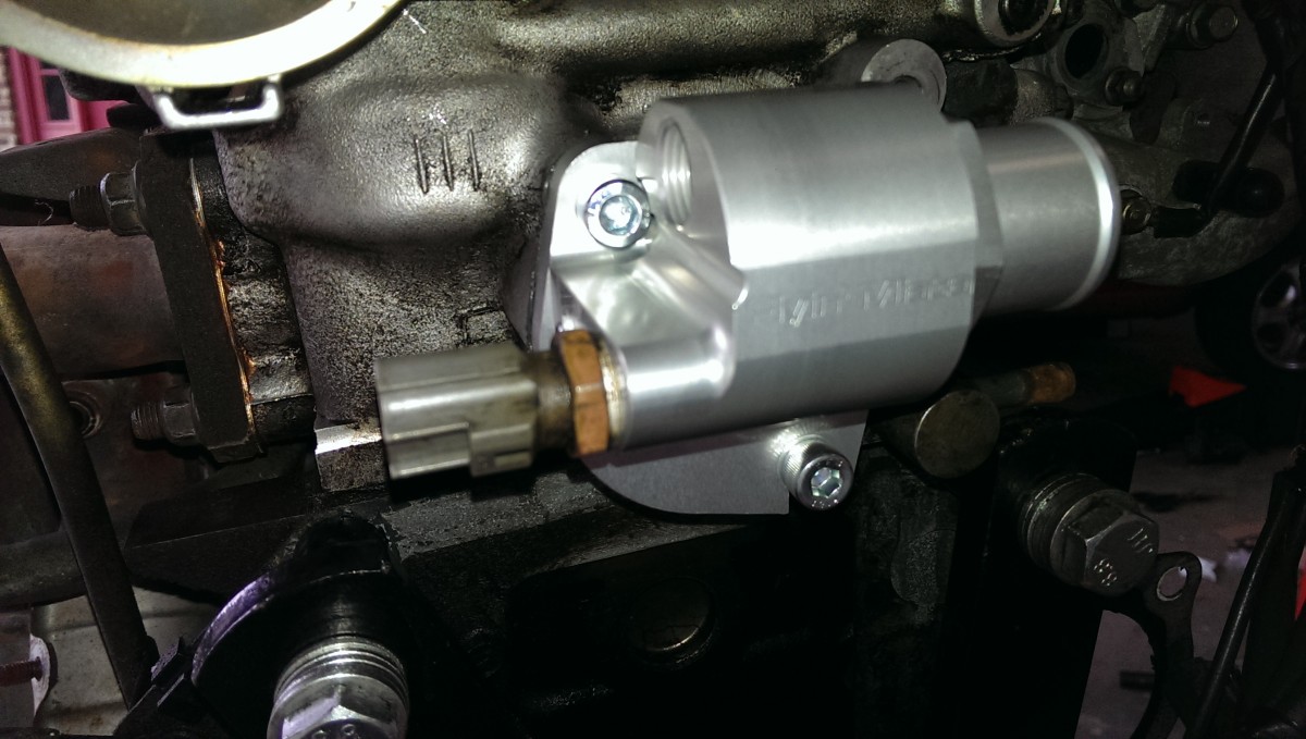
Bolt on the cover
Now the moment of truth. This is super easy with the engine out, but more difficult with it in. There are two allen bolts to install the cover. If you have the room I did, it’s not a bad idea to use a hex bit with a torque wrench to properly torque the cover down evenly. Note in the picture you can also see the black RTV oozing out a little bit. I recommend RTV so you only have to do this job once.
If you’re doing this in the car, that’s probably not an option. The M-tuned cover intentionally comes with the lower right hole actually as a slot instead. This gives you a few options for install, but the easiest is probably to thread the lower right bolt in a few turns, then slide the cover down on top of it, install the top left bolt, and incrementally tighten each bolt down to finish it. In any case, it ultimately needs to look like the picture (except with the heater core fitting on.)
If you got this done with the engine in the car, congrats. That was the worst part, and it’s downhill from here.
Extending the Coolant Sensor Plug
The coolant sensor wire needs to be extended a little bit. The new cover moves it just enough to make the original wiring not quite make it. I’m sure people have just used crimp-on connectors, but I like to solder things properly where possible. Crimp-ons could be a good choice, I guess, if you’re doing this in the car and don’t have enough room, but I suspect that shouldn’t be an issue since the soldering would be done in the intake area.

The plug after soldering wires to extend it
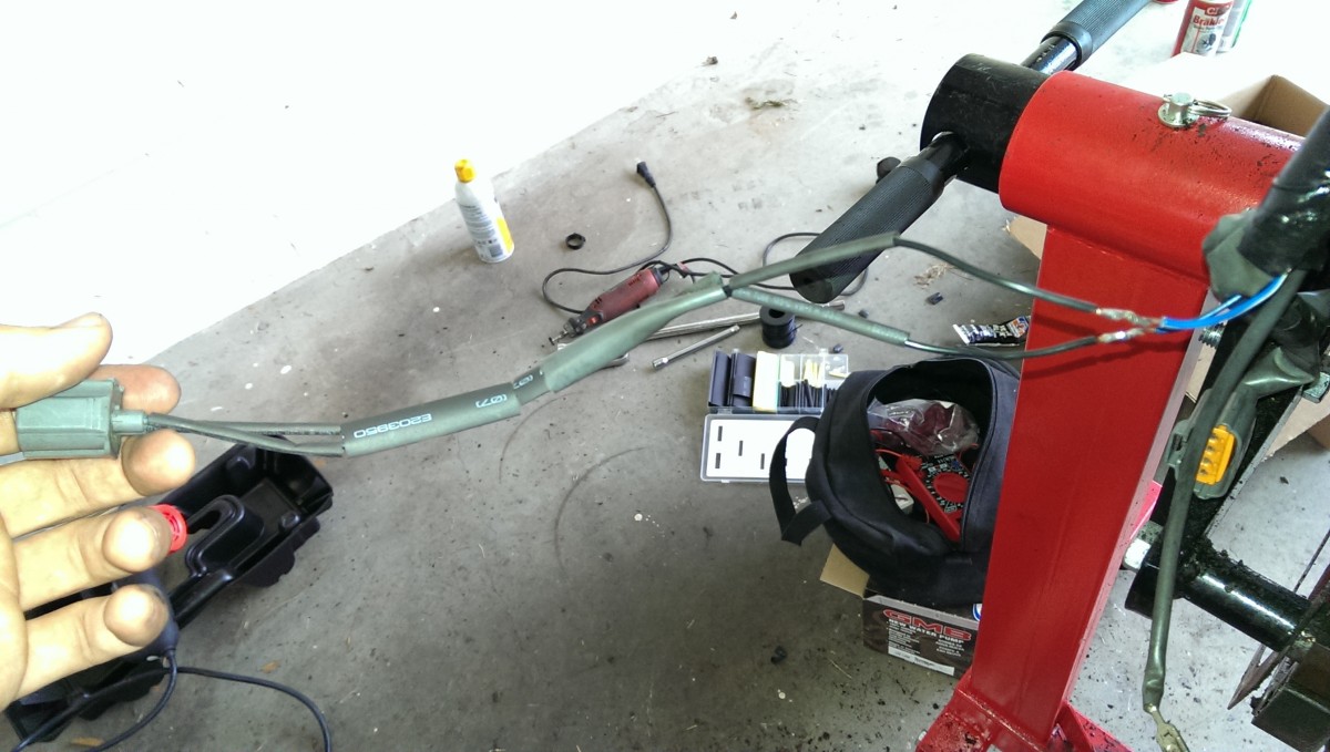
Connection is soldered, ready to heat shrink the tubing
The first step was to cut and strip the existing plug wire. I then soldered some extra wire I had laying around to both leads, to extend them about 8 or 10″ or so. I then picked out some heat shrink tubing

Heat shrink and soldering all done

Coolant sensor plugged back in
Once the soldering was all done, I moved the heat shrink tubing over the relevant sections of wire and shrank it down with my heat gun. A hairdryer or lighter can work for this too. The final shot shows it all plugged up and ready for business. I think it’s worth doing a proper soldering job, because crimp-on connectors and wire nuts won’t last nearly as long in an automobile application where there is constant vibration and movement.
Reconnect the heater core hose
The heater core hose needs to be reattached to the port just above the coolant sensor in the above picture. If it doesn’t go on very easily, I’ve used some silicon or other lube in the inside of the rubber hose and the outside of the fitting. It should just slide on if the heater core hose is relatively new, such as if you had to cut it off and replace.
Capping the front water neck
The next step is to remove the original thermostat and front water neck, replacing it with a cover to cap it off. This step is much easier. This will cap the water neck that comes out past the timing covers. If desired, you can instead buy and install a separate cap that goes right against the head of the motor, making a cleaner look and slightly more engine bay room.
However, this requires the work of a water pump and timing belt job. I was that deep in this engine when I did this, but I decided to just do the vanilla water neck cover as pictured because I plan to eventually drop in a built motor, and I want to be able to pull the reroute off of this one without any more work than necessary.
Pull the old thermostat cover
First, the old thermostat cover comes off. Just like the rear, this is actually two studs and two nuts, not two bolts. You can use the same double-nut trick to remove the studs after the cover comes off. Your thermostat will be in here as well. You can throw it away or keep it if you want to go back to stock later – it isn’t required for the reroute.
New cover after RTV on the stick-on gasket
Again like the rear cover, this one has a stick-on gasket that I again used RTV on. I was never able to get the water neck surface clean enough for a gasket to stick without RTV to help, so I don’t even try anymore. I’ve also seen forum posts recommend RTV red, which is high-temperature. The problem I’ve had with red is that it takes a long time to cure, and it’s hard to get the water neck totally dry. I prefer ultra black everywhere.
On this one, I definitely would torque it down evenly with a torque wrench and allen socket to spec because it is easy to get to. If you would rather and used RTV, you can probably risk it by just using an allen wrench and torquing it as evenly as you can.
Plugs in after thread sealant
Lastly, put some thread sealant on the two plugs, and screw them into the cover. I did this after installation because these two bolts are very easy to get to and having it be installed holds the cover while I tighten.
Install the Thermostat

Thermostat and housing
The big port on the rear cover connects to a small bit of hose that connects to the thermostat housing. The above picture shows the housing, in two pieces that twist together, along with the new thermostat and some silicon grease, like you’d use for plumbing. The first step is to put this together. I have some details on which thermostat to use based on your configuration at the end of the article.
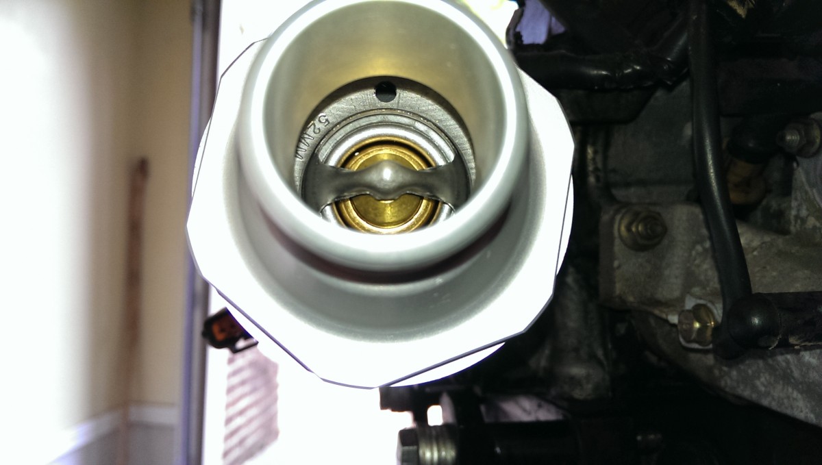
Orientation of thermostat in housing
The most leaks people have had are with this housing. Fortunately, there’s an easy solution. For starters, I put a decent amount of silicone grease on the rubber gasket that goes around the thermostat prior to installation. This both prevents the rubber gasket from tearing as the two halves are screwed together and also helps keep water from passing through the seal between the aluminum housing and the rubber gasket. Secondly, this may be unnecessary, but I also put a few drops of the Permatex thread sealant I used earlier on the threads of the housing before screwing it together.
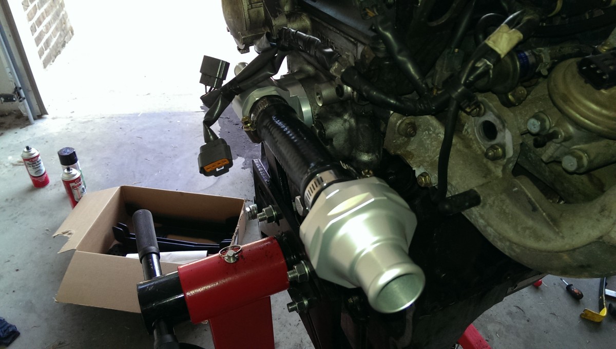
Housing and thermostat installed
Once the housing is together, it can be installed. The kit ships with a shorter piece of tubing intended to go from the large port on the rear cover to the intake side of the engine, where the housing fitting is installed in the tube. Both ends of the tube are sealed with simple hose clamps.
One caveat here is to make sure that the thermostat is oriented correctly, as in the second picture earlier. The first important thing that the spring faces TOWARDS the engine, the other side (pictured) faces TOWARDS the passenger side of the car / the radiator. Additionally, when installed, the goal is to have the pinhole at the top, to help remove air from the system later on.
Optional: Replace throttle body coolant lines
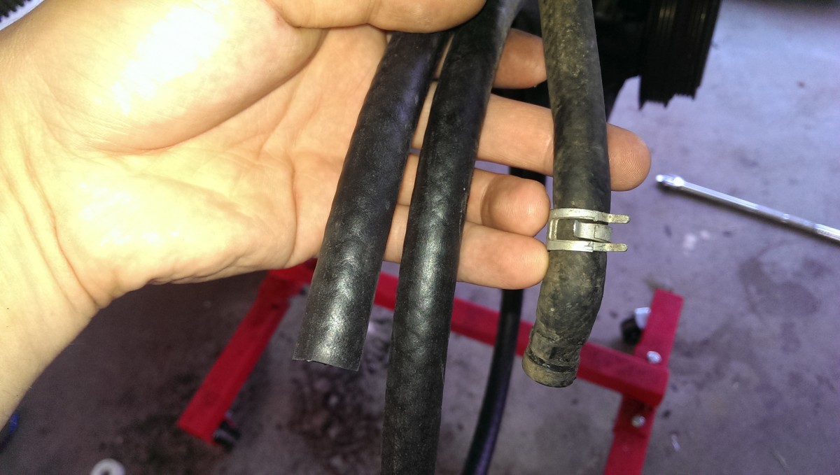
Fuel line can replace the throttle body coolant lines
The throttle body has some coolant lines that go through it. Some guys delete these, but I left them. If you leave them and the lines have been disturbed or are old, this is a good time to go ahead and replace them. Some cheap fuel line in a matching inner diameter does the job perfectly.
Install final hose
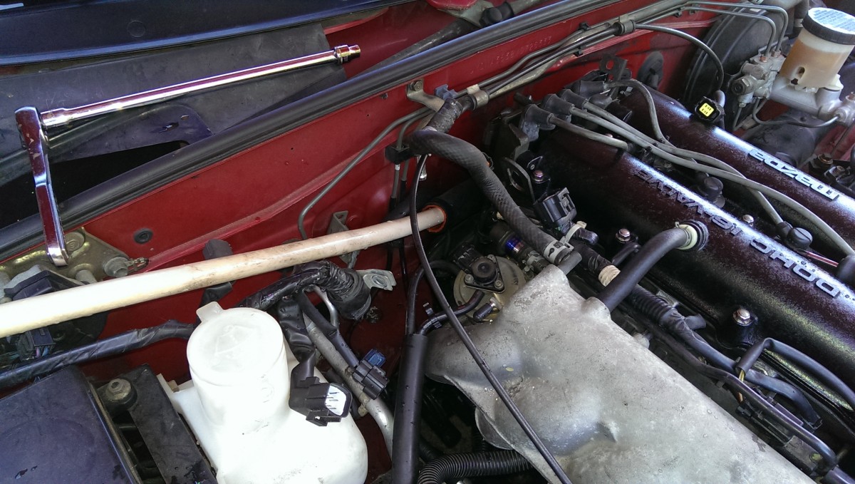
The stock line fits poorly, at least on my 97
Lastly, there is a long hose and a spring. The spring is placed inside the hose to keep it straight. The hose is then attached, using hose clamps, to the thermostat housing, run around the intake, and attached to the radiator. Additionally, the guide recommends zip-tying the hose to secure it, anything in the vicinity that looks secure should work.
There is more hose than required. This is good, because you should use pieces of hose (cut open lengthwise) ziptied around the hose anywhere it may rub on anything metal or sharp to prevent it from getting split open.
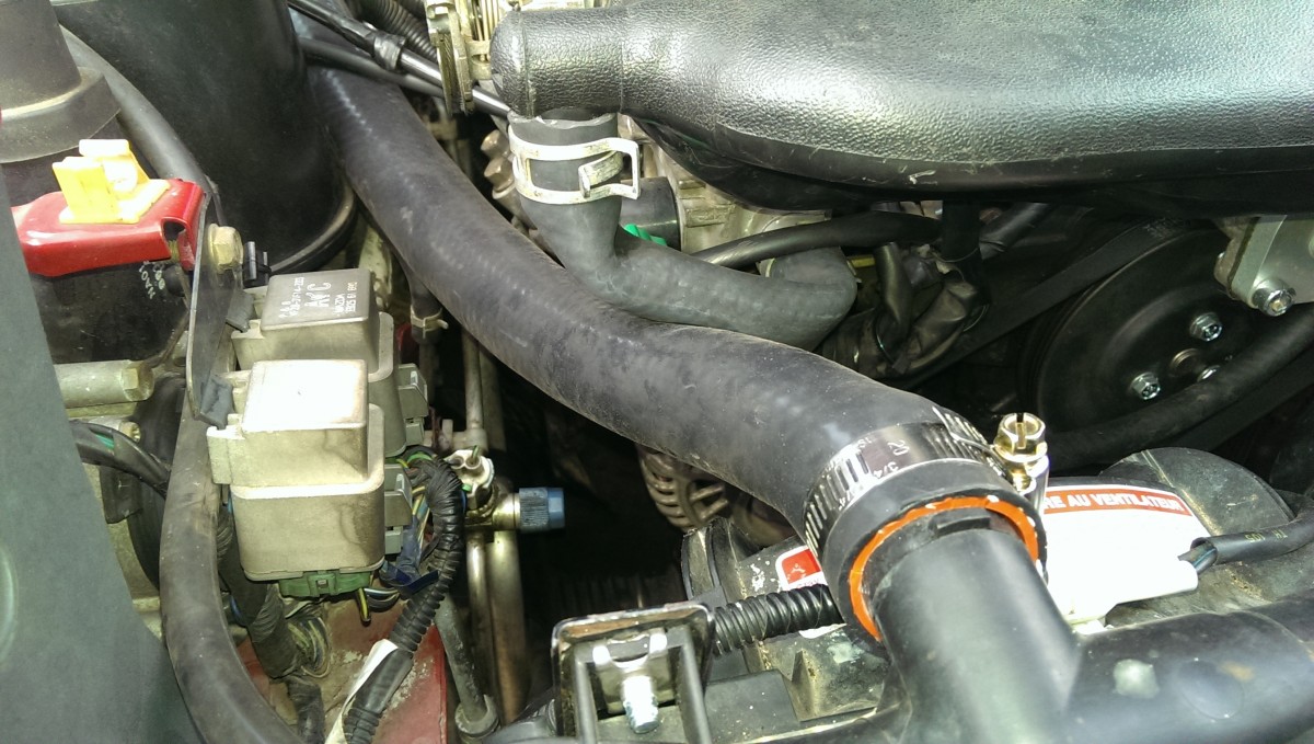
Depending on your intake, this may work fine. On a stock 1997, one of the intake hoses gets in the way of the coolant line, producing the result pictured. Certain turbo setups have a similar issue.
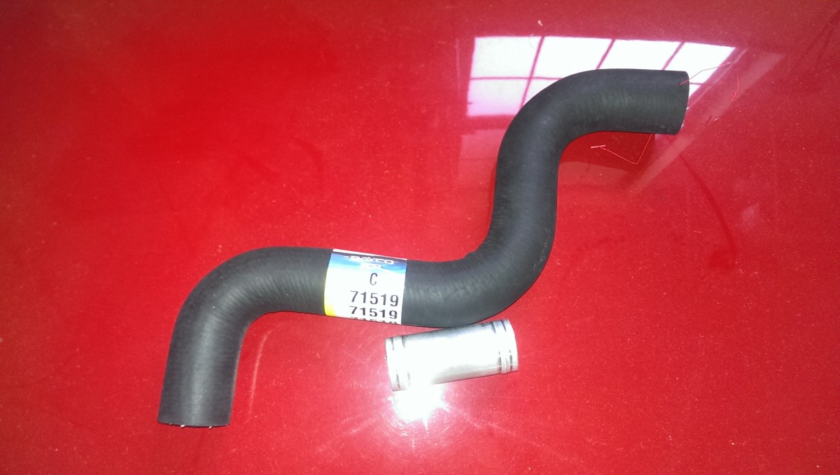
This part will fix the issue
The fix is to get a kinked hose like the one pictured. That is Gates part number 22165
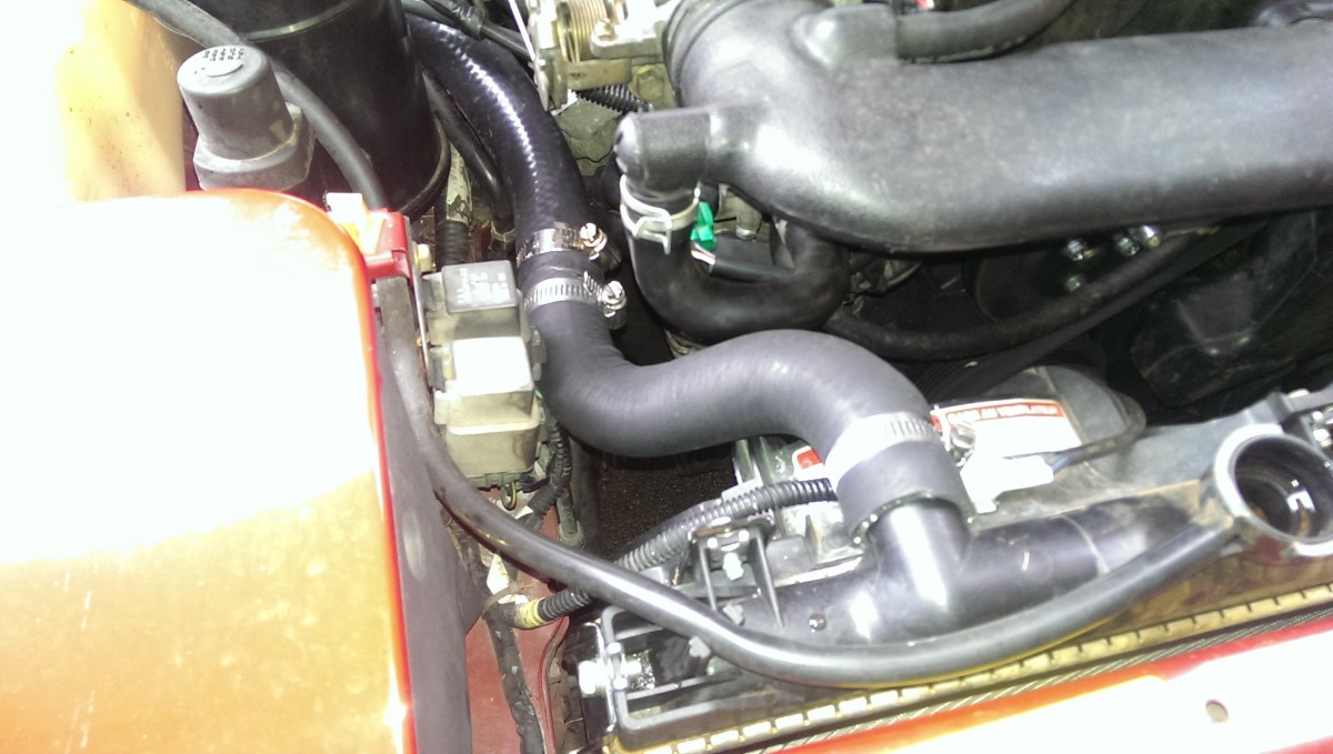
Rerouting fixes the issue entirely
With all the hoses cut down and clamped together, there is no longer a kink in the line and the installation is done. Now you can fire it up and check for leaks.
Flushing
Flushing with a garden hose
One tip is in how to flush the radiator with the reroute installed. Normally, you’d pull the cover off the water neck, remove the thermostat, and run a hose there with the radiator drain valve open until the water runs out clear. However, the reroute changes all that. It’s still very trivial, however.
Simply drain the radiator and leave the valve open. Then, undo the engine side hose clamp on the housing and pull it out. You may still have some coolant left in the line, so be sure to have a bucket or cup to catch it. You can insert the hose into the short piece of line that goes into the rear cover and flush that way.
Thermostat choices
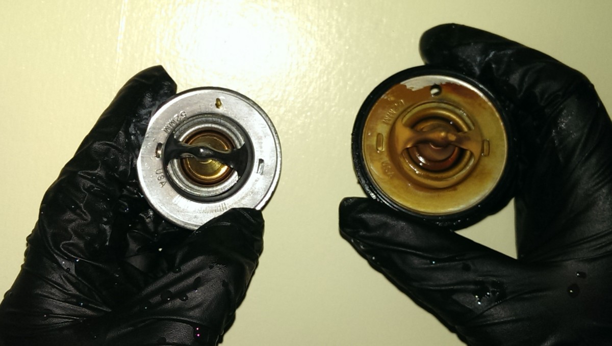
Factory thermostat on left, kit thermostat on right
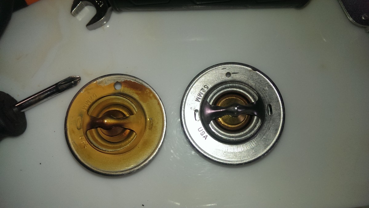
Kit thermostat drilled to 1/8″ on left, 1/16″ on right
One issue with this reroute is that the thermostat is no longer right on the back of the head. This is excellent for serviceability, but it’s an issue for the thermostat itself. The water temperature at the thermostat will now be slightly lower than it is in the engine, and there may be a delay getting the thermostat to open. As a result, m-tuned’s solution is to drill out the thermostat jiggle pin to allow a little more coolant to flow when the thermostat is closed. This evens out the delay in water temperature reaching the thermostat, mostly, and helps with the issue.
Stock, the kit ships with a 195F thermostat with an 1/8″ hole where the jiggle pin originally was, pictured. This is a Stant 13959
Replacement parts:
Thermostat seal (rubber o-ring / gasket): Stant 25270
Some people have said its a Stant 25280, this is WRONG. It is too small and has to be stretched, it has rounded instead of squared edges. It looks like it’ll sort of fit, but it will not seal correctly.
Thermostat comparison on my naturally aspirated 1.8L ’97:
Stock 195F Stant 13959
Stock 180F Stant 13958
Stock 195F Stant 13959
Stock 195F Stant 13959
Burping the Coolant
Once your car is back together and ready to run, you need to fill and burp the cooling system. You want to get as much air out as you can, because an air bubble will block coolant circulation. Additionally, if you get a bubble near your temperature sensors, the ECU will misread the current temperature.
Here’s how I do this:
- Fill the radiator with coolant
- Raise the nose of the car on jack stands
- With the radiator cap off, start the car
- Let the engine idle for a good 30 minutes or more
- As the engine gets warm, the thermostat will open, the coolant level will drop, and air will be pushed out
- Each time this happens, top off the coolant
- You can squeeze the long reroute hose to help release air bubbles from there
- Once complete, top off the overflow tank. As you drive the car for the next couple of weeks, keep an eye on the overflow tank, topping it off as necessary.
I find that if I try to burp the car with the nose on the ground, it’s a lot harder to get all of the air out. This is especially true with the reroute, as the soft hoses trap air more easily than the stock configuration. You also want to monitor your connections and make sure you haven’t introduced any coolant leaks.
As far as coolant goes, the factory manual recommends 50% antifreeze and 50% water. This is fine for general street use. If you track your car, you may want to drop to as low as 30% antifreeze, as more water does a better job cooling. If you run a pure track car in hot environments, you may consider just water with “water wetter” to help corrosion; water wetter contains the anti-corrosion additives you’d ordinarily get from antifreeze.
I usually just run by Walmart and buy Prestone or whatever concentrated coolant
If you don’t want to deal with mixing the coolant yourself, you can buy 50/50 premix
One last safety note, never pull the cap on the radiator with the engine hot! It will steam and boil out.
Conclusions
On the whole, this kit has been great. It has helped even out the cooling between cylinders and keep my temps down on the track. Dialing in the thermostat takes a little bit of doing, and the remote housing is a little bit ghetto, but it works well enough that fixing the cooling flow to its intended configuration is completely worth it.
[…] instructions that Flyin’ Miata provided were pretty good, but I also used the write up here at Did It Myself for further guidance. I’m glad I used thread sealant rather than thread tape, and the […]
Can you add a bit to this on how to properly burp a re-routed system? I read a number of conflicting posts on this – some claim ‘the same way – raise nose of car’ others ‘keep car level’.
Great idea, I just added it. In general, especially with a reroute on, I greatly prefer to raise the nose of the car. It helps move the air out towards the top of the radiator.
Very nice write up, thanks. I added a 90 degree hose with a metal coupling at the back, I don’t know why it wasn’t included in the first place. Both Pegasus Racing and Summit carry them, both are high quality silicone hose.When you installed the engine/transmission, did you keep the rear water opening cover in place? As it sticks out farther than the coil packs and CAS, I’m taking mine off and will re-install when the engine is in place.
Thanks, glad it was helpful! I took my coil pack off, but left the CAS and rear water neck / covering in place. For what it’s worth, I found its easy to bang the coil pack on the firewall and they’re pretty easy to damage. The water neck is too annoying to install after the engine is in, though. I definitely prefer installing it and get it sealed before putting in the motor .