K24 Miata Swap – K24A2 Engine Internals Prep
The Kmiata kit appears well-engineered, the welds and machined parts look fantastic, and the customer service response time has been excellent. That said, the build instructions are a little… sparse. So here’s a more thorough guide to K24A2 engine internals prep, including replacing the oil pump, timing chain tensioner, cam gear, and oil pan in preparation to drop a K24A2 into a Miata.
See All K24 Swap Articles: K24 Miata Swap Main Page
KMiata has a YouTube video showing this process. I recommend reading this article, watching that video, and then using both when working on your engine. When I went through this process, I found several critical steps were glossed over, but the parts the video shows are very helpful.
Stripping the Motor

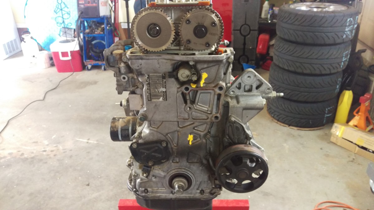
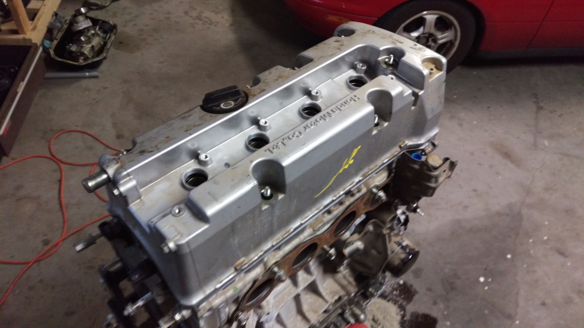
The motor as it arrived, on a stand
Here is the motor as it arrived. It is a K24A2 out of a 2008 Acura TSX with 72,500 miles on it, and it cost me $874 including tax delivered to my house. The first step is to pull off all the extra parts until the manifolds are gone. I’m not going to document this part because it’s really just “pull it all off.” If this step is too much for you, you might want to get some help to perform this swap, and I don’t mean that in a condescending way.
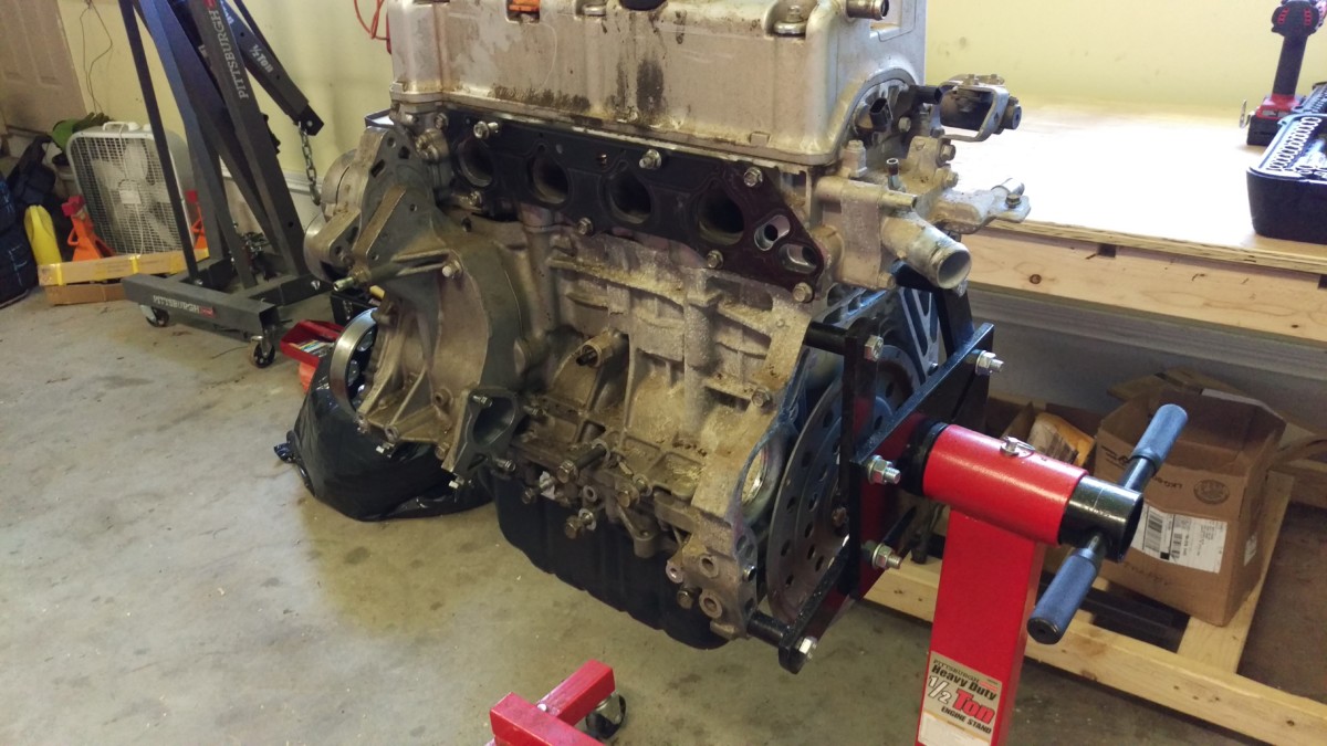
Ready to begin
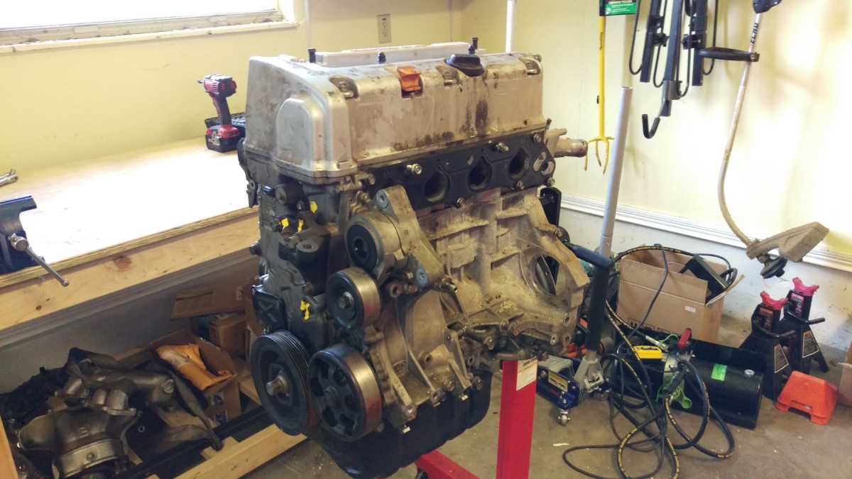
Another view
Once you get it down to this point, you’re ready to begin.
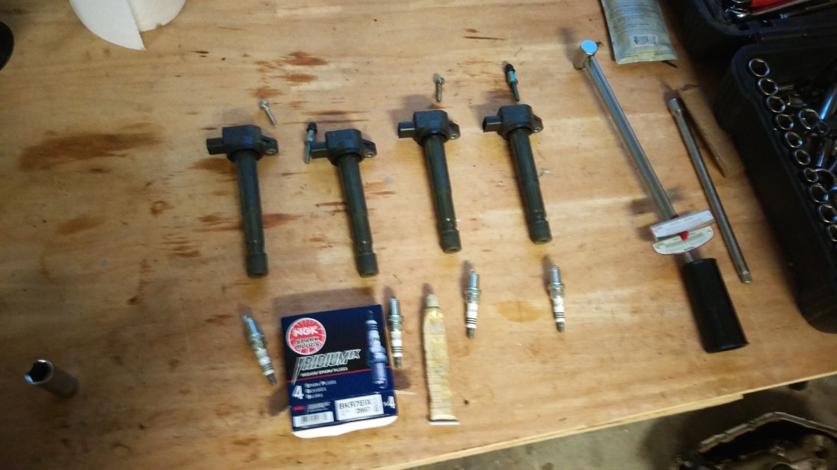
Lay Out Your Parts

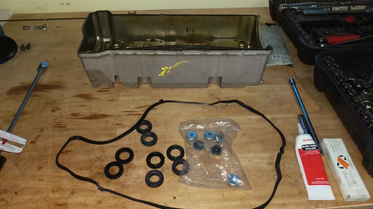
All the parts on my bench
You’ll want to lay out all of the parts you’ll need and make sure you have everything. Make sure you have:
- Replacement oil pump
- KMiata oil pump half (black anodized)
- Oil pump bolts (package with about 9 bolts in it)
- Valve cover gasket
- KMiata oil pan
- 50 Degree cam gear
- New oil chain tensioner
- Honda Ultra Flange
(or you could probably use Permatex Ultra Grey
)
- Honda Crank Pulley Holder

It’s also very helpful to have some kind of impact wrench. I use an electric Kobalt

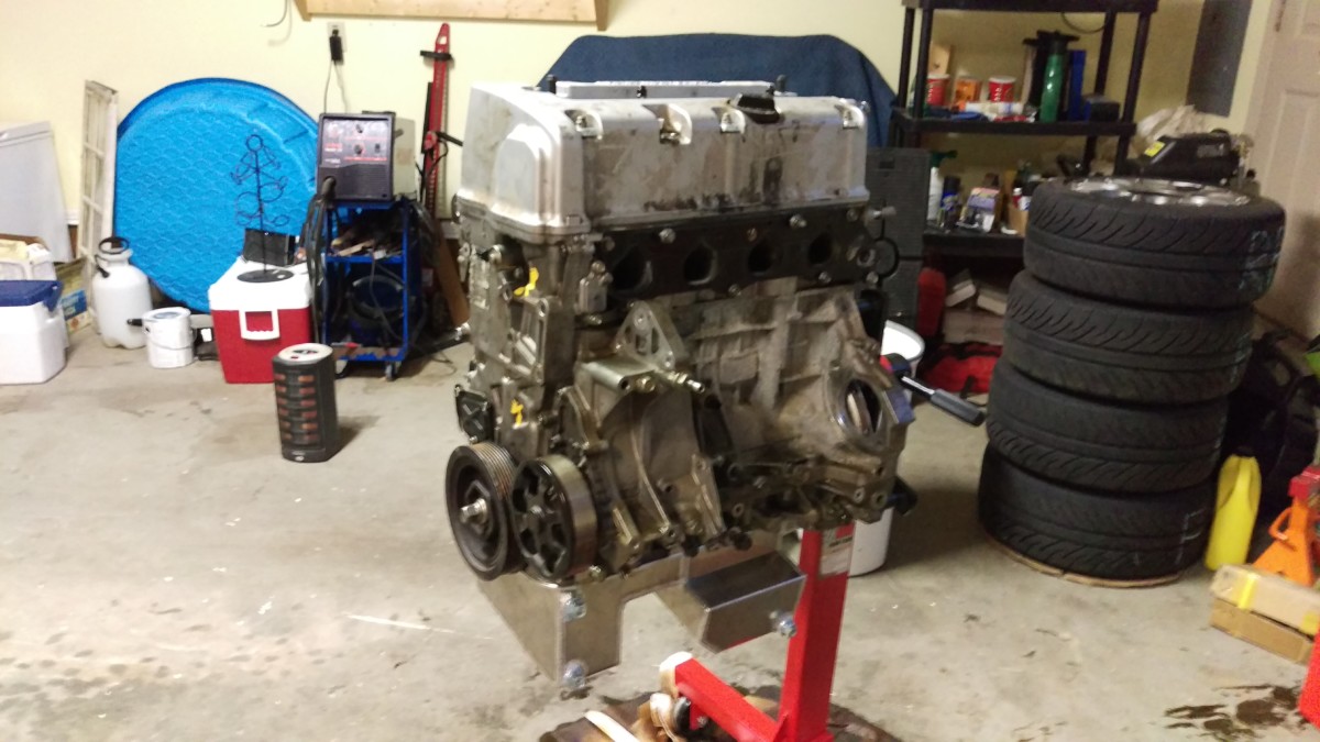
You should have the engine on a rotating engine stand
Remove the Spark Plugs and Drain the Oil
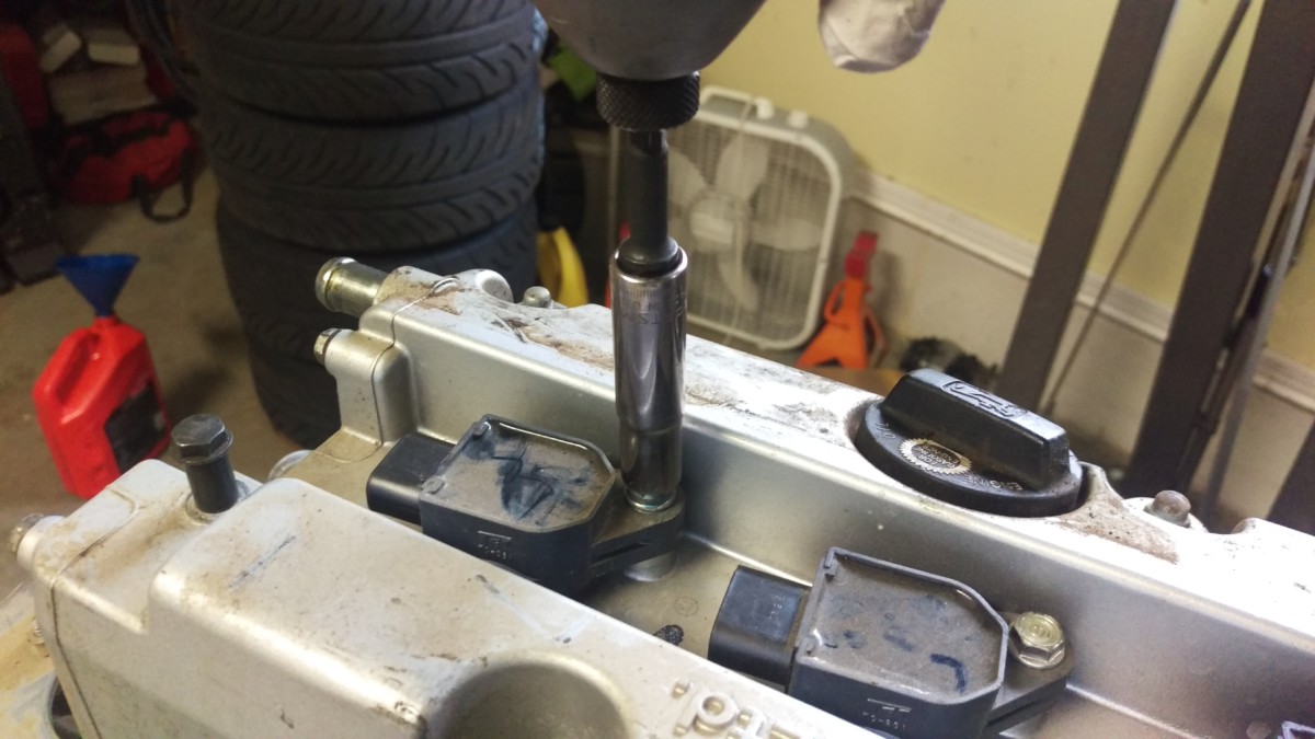
COP Bolts
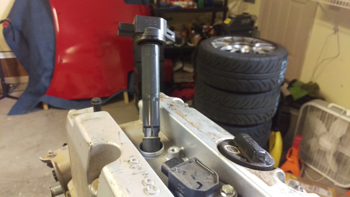
Pulling COP out
You’ll now want to remove all four spark plugs. For each plug, remove the coil-on-plug connector bolt as shown. Then, the COP will simply pull straight out.

5/8″ spark plug socket and extension
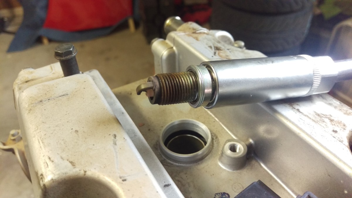
Removed spark plug looks good
Then, using a long extension

Removing the Valve Cover
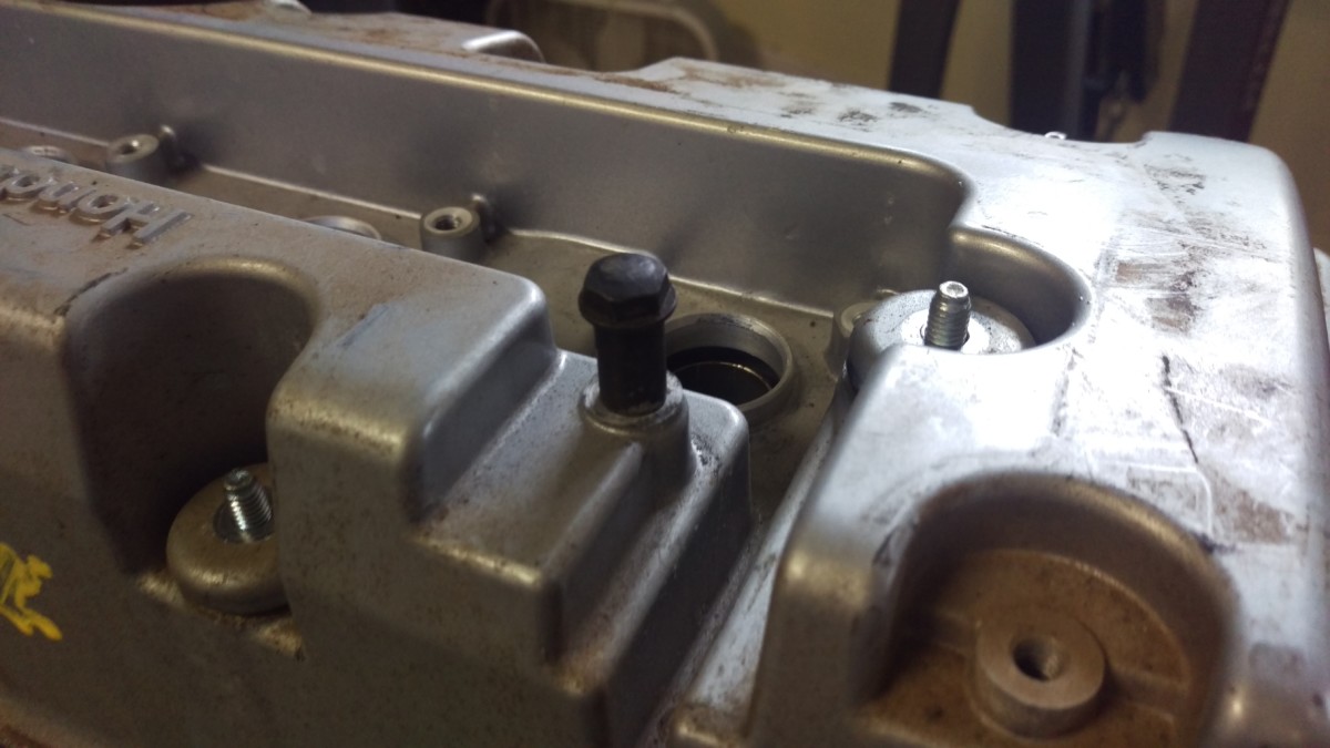
Remove all of these small valve cover nuts
The next step is to remove the valve cover. On the k24, these are really nuts that thread onto studs in the cylinder head, as opposed to the valve cover bolts I’m used to seeing.
Valve cover removed
Once all of the nuts are out, the valve cover can be lifted off. There shouldn’t be much RTV under the valve cover, so you should be able to pull it off fairly easily.
Remove the Old Belt Tensioner
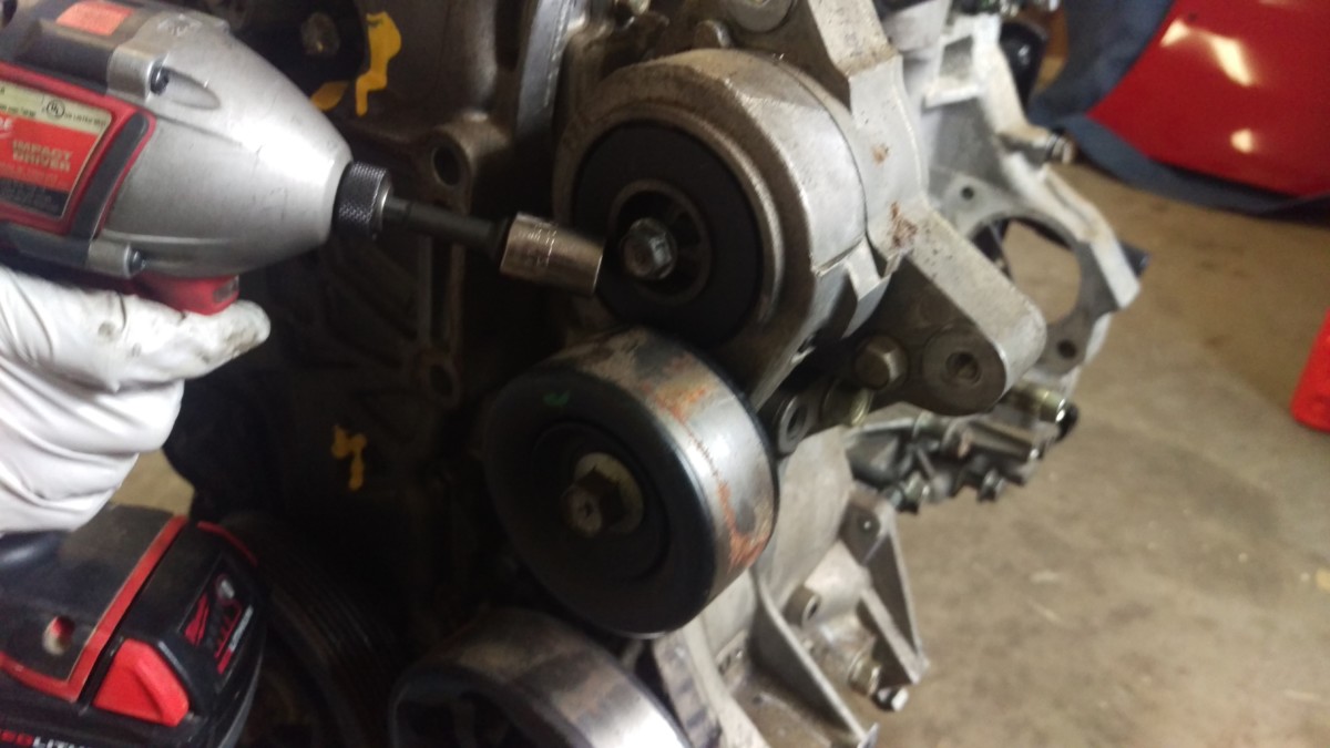
Center bolt
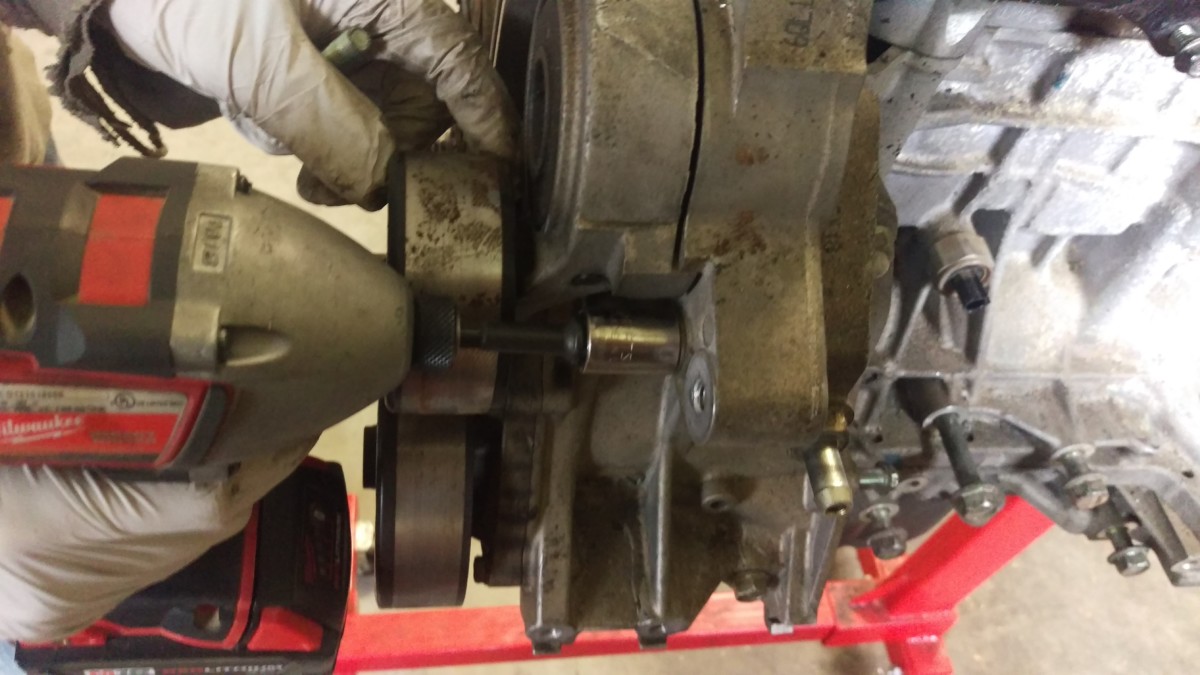
Right bolt

Left bolt
The belt tensioner comes out after removing three bolts, if you didn’t already take it off. I hadn’t. It won’t actually be used after the swap, because the KMiata swap kit includes a new belt routing system that tensions using washers on the alternator. It’s a little kludgy, but it’s supposed to work.
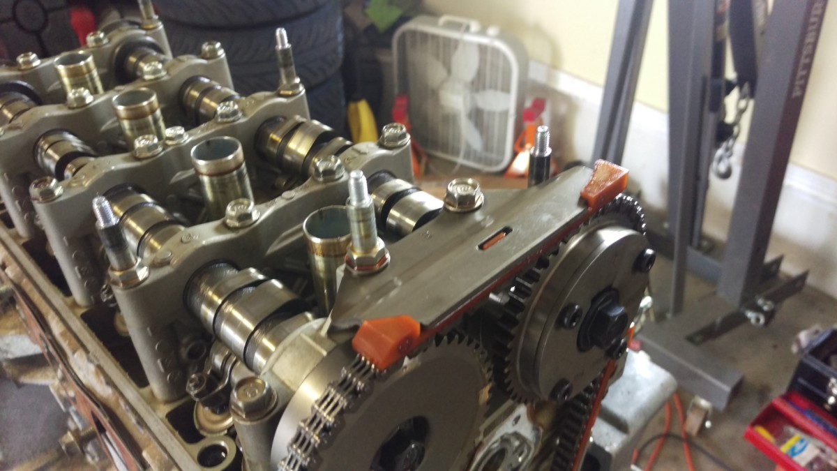
Align the Cam Gears
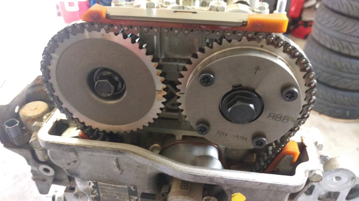
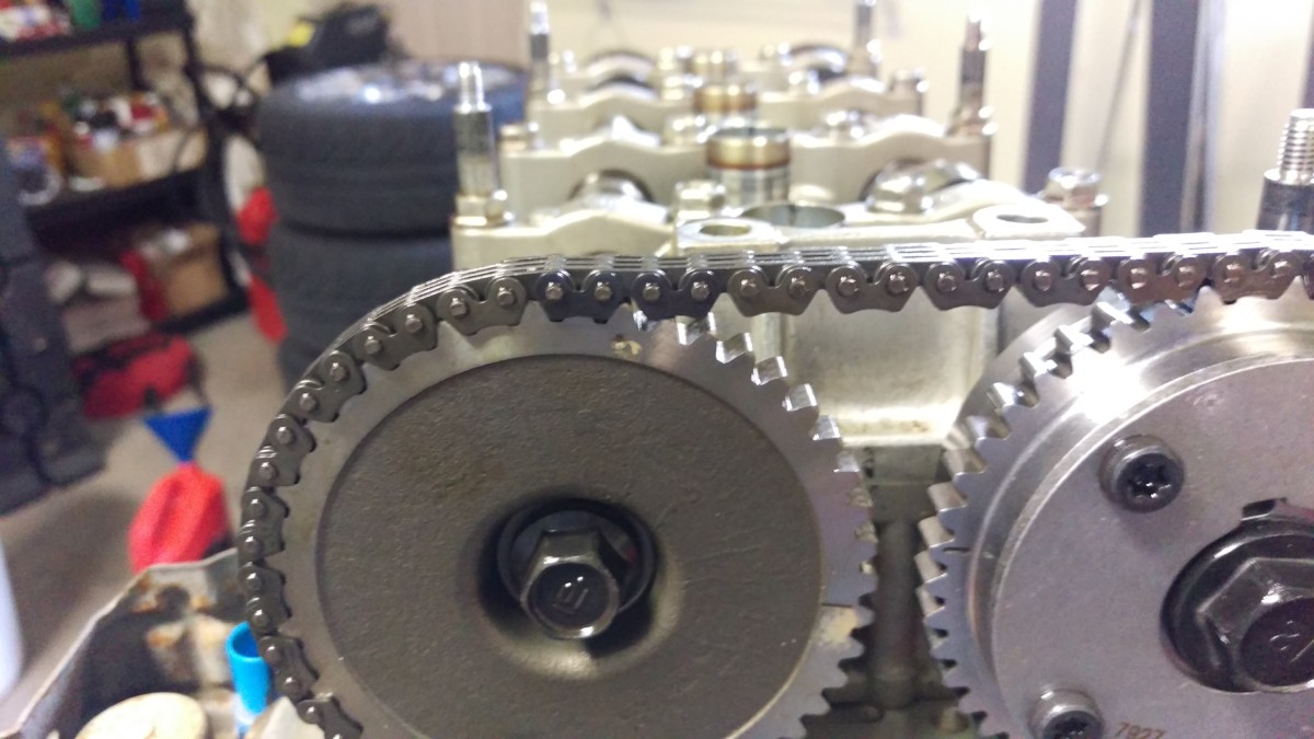
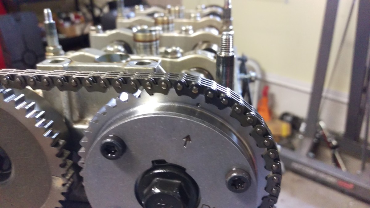
The dashes should point to each other, with the arrows almost pointing up
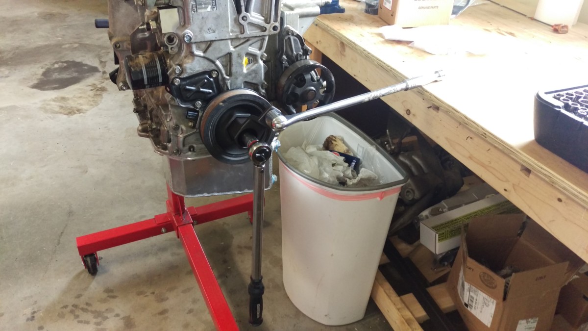
The next step is to get the cam gears in alignment. It’s important that they stay in the alignment for the rest of the job. This is an interference engine, so you do not want to mess up the timing or rotate the crank or cams independently of each other. Fortunately, Honda has made this easy. Put a 19mm wrench on the crank bolt, which is right in the center of the crank pulley. Spin the bolt clockwise, rotating the engine, until the cam gears line up as shown. The two dashes should point at each other, and the arrows should point up. Leave the crank and cams in this position until this job is almost done. A few degrees of movement of either of the cams either way is almost unavoidable, but you do not want to actually spin them through full rotations.
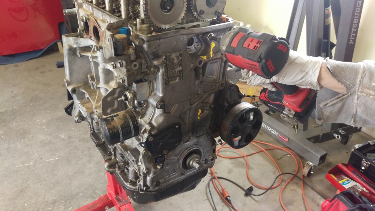
Removing the Crank Pulley
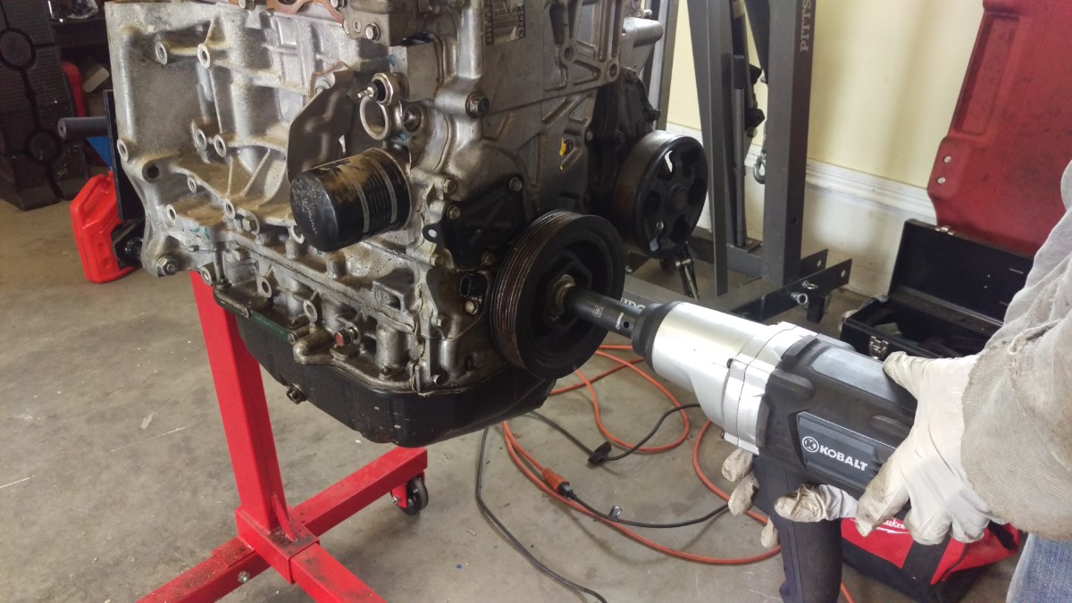
I used an impact wrench
You can remove the crank pulley next. First, the crank pulley bolt needs to come out. I used my Kobalt electric impact wrench

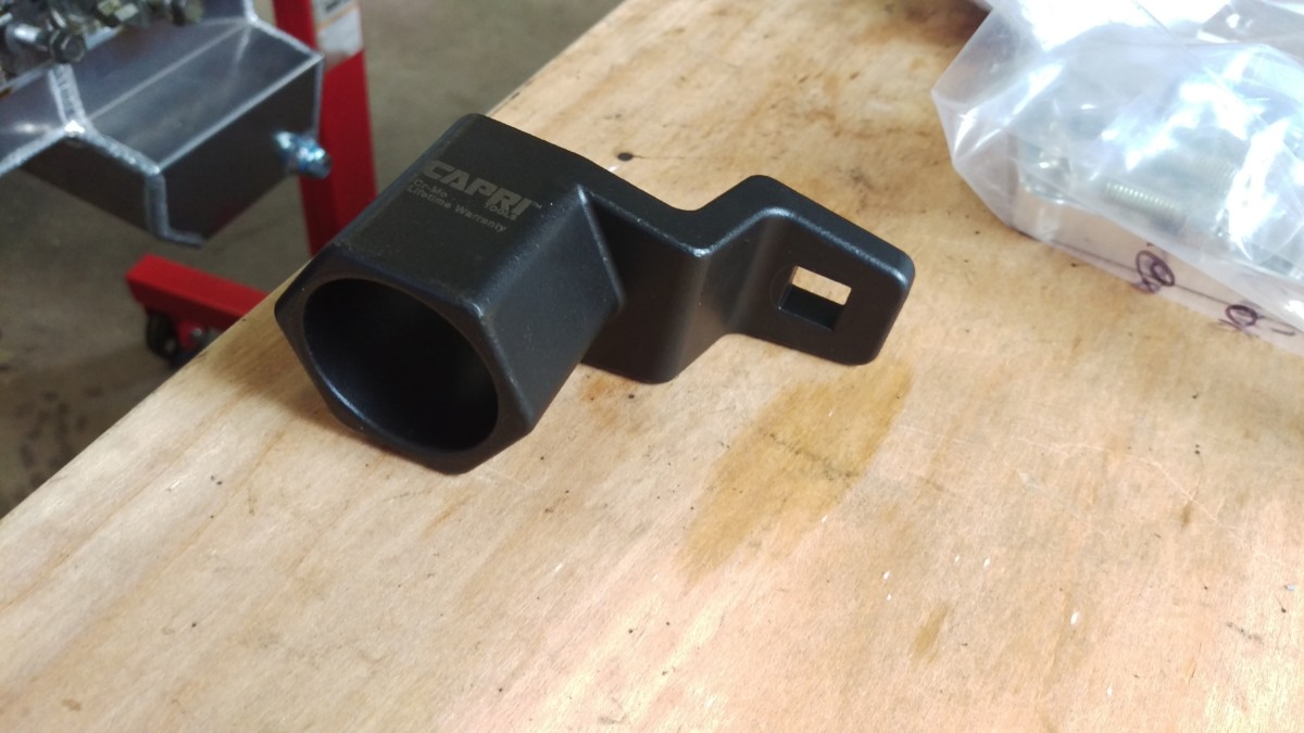
Honda crank holder tool
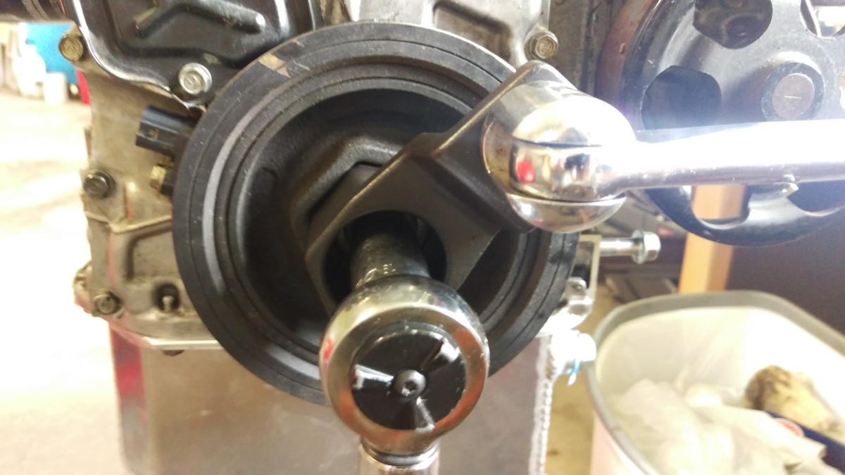
Using holder tool
If you use the honda crank pulley tool

With the bolt removed, the crank pulley should just pull off
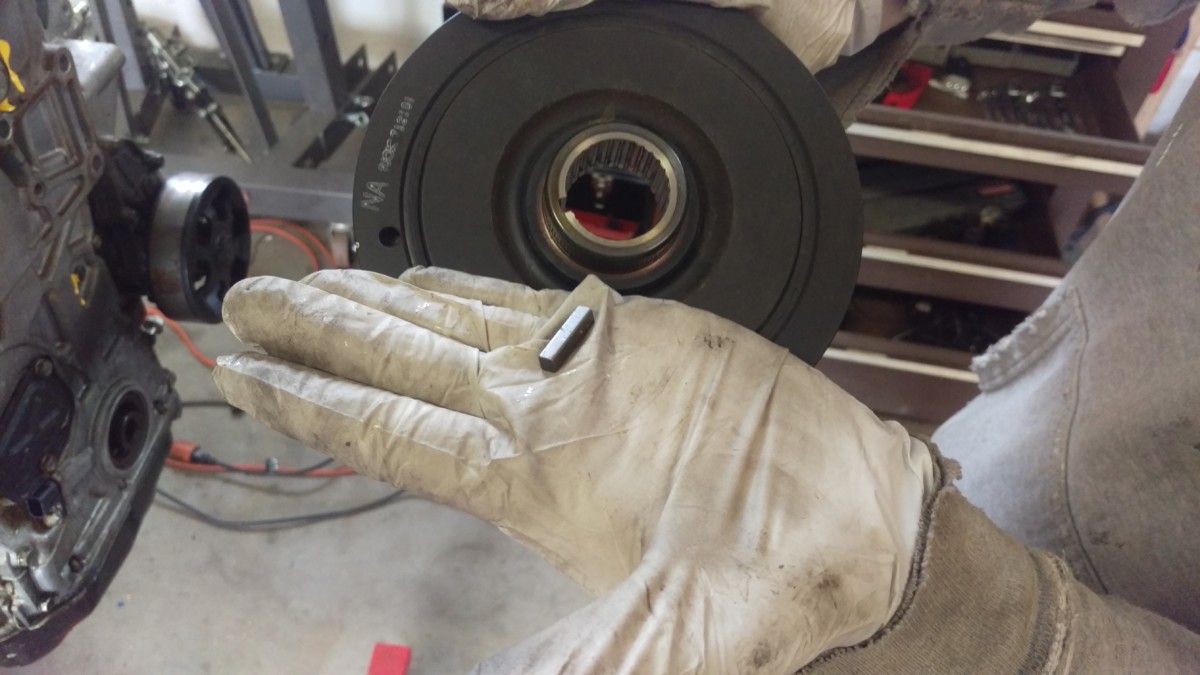
The woodruff key will fall out
Once the bolt is removed, the crank pulley just slides off. There will be a woodruff key, which is the name for the little piece of metal that sits in the notch between the pulley and the crank. Don’t lose track of this. The crank pulley and woodruff key can be set aside for the rest of the job.
Remove the Timing Cover
Ready for timing cover removal
At this point, the timing cover can come off. The cams should be lined up with the dashes facing each other, and the crank pulley and bolt should be removed.
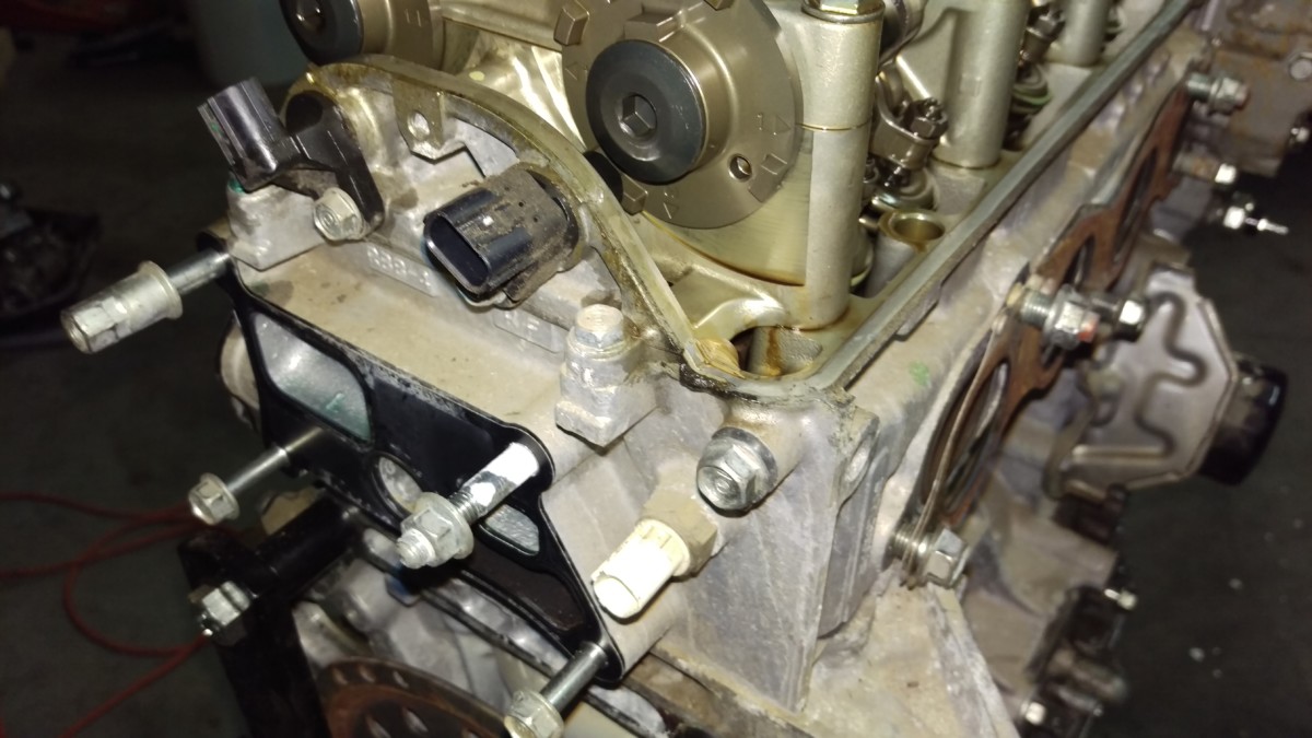
This solenoid needs to come out first
This solenoid needs to come out first. After removing this bolts near it, it simply pulls out. This is demonstrated in KMiata’s engine prep video. Some oil will leak from the hole – this is normal.
Remove the remaining 10mm bolts around the cover
I didn’t document them all, but you also need to remove the remaining 10mm bolts holding the cover to the block. There are probably 8 to 12 of them. Don’t forget the three bolts underneath the timing cover, at the front of the oil pan.
Also remove this 14mm bolt
This 14mm bolt needs to come out as well.
Pry off the cover
Once all of the bolts are removed, you should be able to pry off the timing cover. This will take a little bit of force, since RTV will be holding it on. However, it shouldn’t be all that difficult – a decently thick screwdriver should do it. If you’re really having to force it, double-check to make sure you got all of the bolts. Also be careful to pry in an area that does not have a sealed mating surface – you want one of the areas where the cover sticks out over the outside of the block. Don’t gouge the surface used to mate the cover to the block.
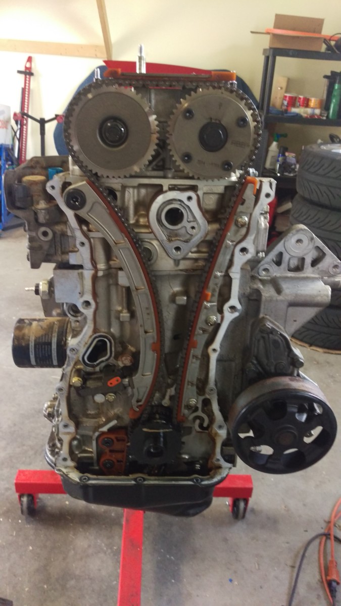
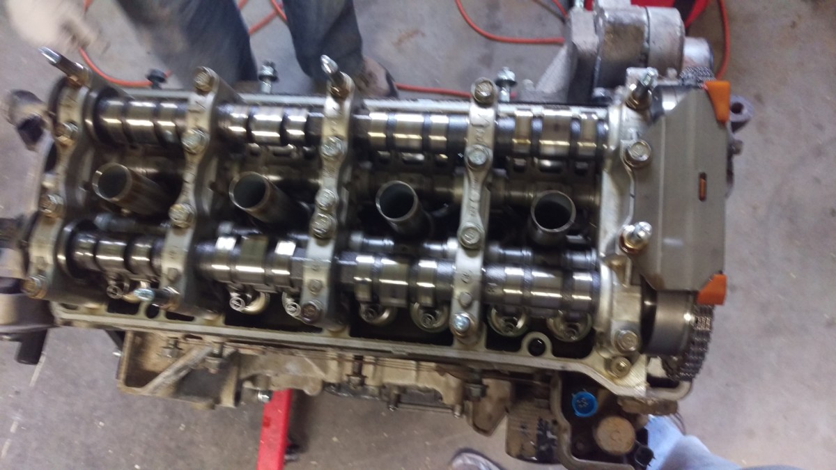
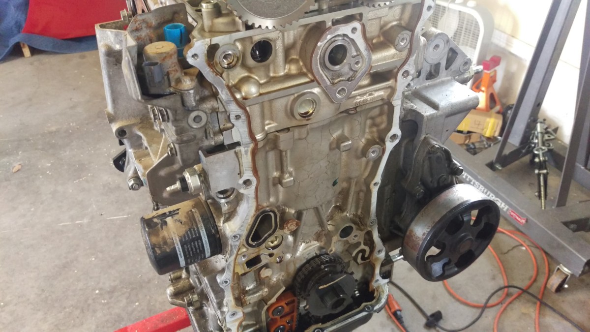
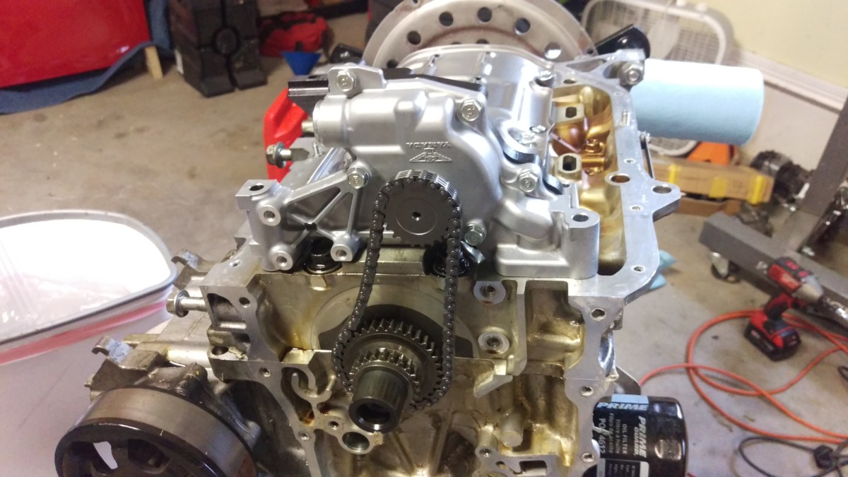
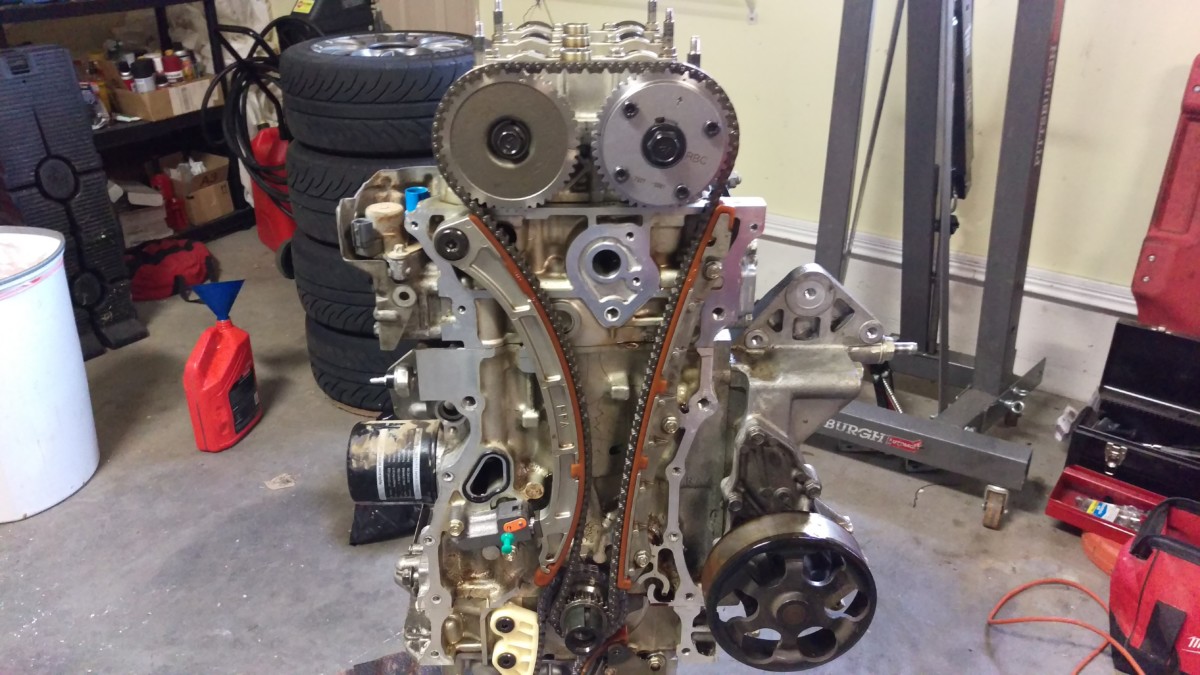
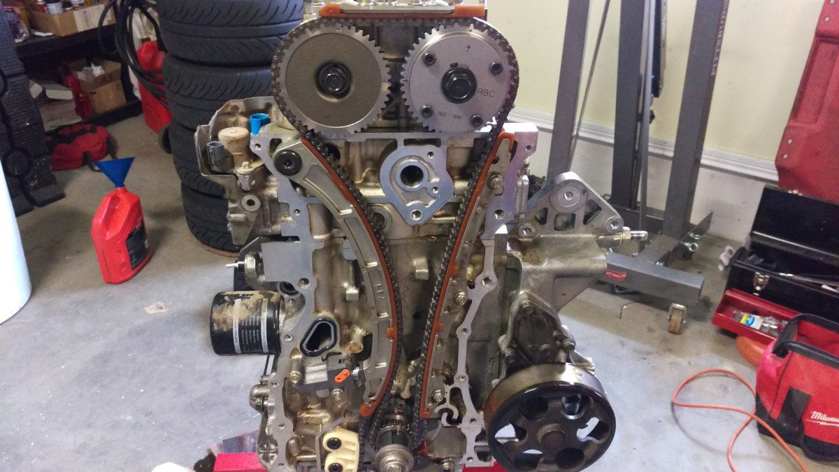
Timing chain exposed
Here is the engine with the timing cover removed.
Remove the Crank Position Sensor Wheel
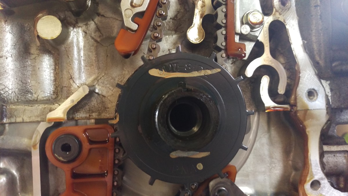
Wheel just pulls off
The K24 will have this trigger wheel for the crank position sensor. This is similar to the 96+ Miata setup, except it’s behind the timing cover and doesn’t get a ton of grime on it all the time. Anyway, it pulls off. It has “outside” on the outside side, and is indexed, so you shouldn’t be able to screw it up on reinstallation.
Remove the Timing Chain
Remove the upper chain guide first
Now it’s time to remove the chain. Start with this upper chain guide. The two long bolts on top are holding it in place.
This chain guide has three bolts
The one on the right side of the engine has three bolts holding it in.

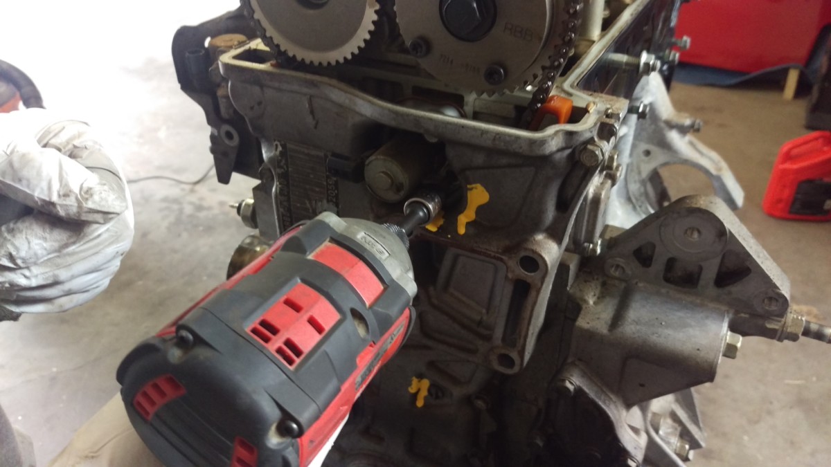
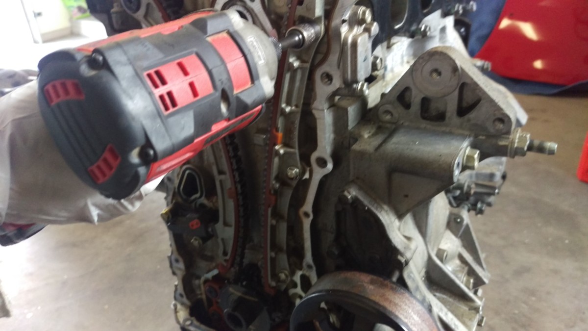
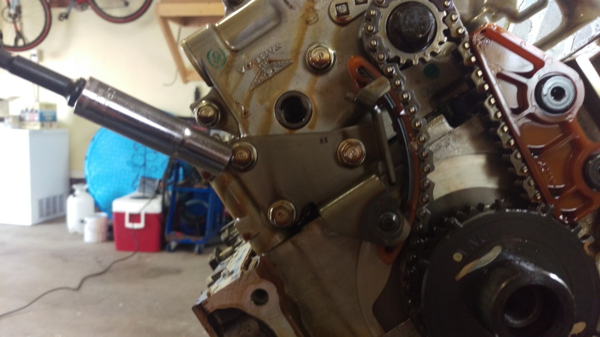
Remove this bolt to detension the chain
Finally, the left side guide and tensioner can be removed. The easiest way is to undo the bolt in the picture with a small impact driver
Engine with timing chain removed
Finally, the chain simply pulls off.
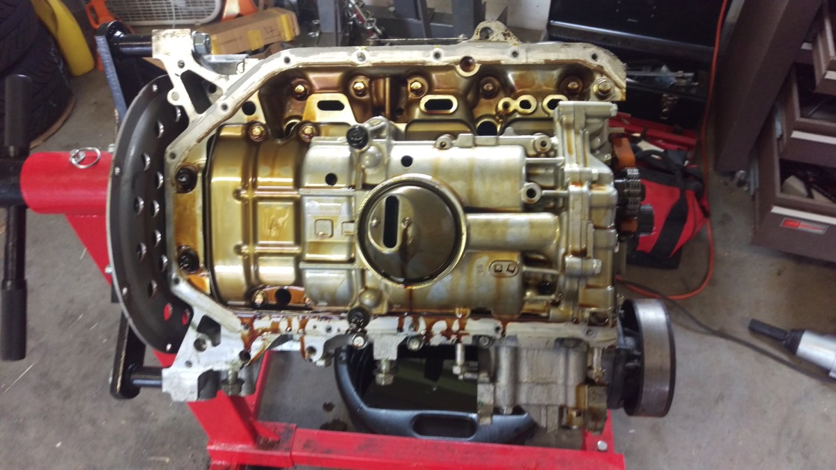
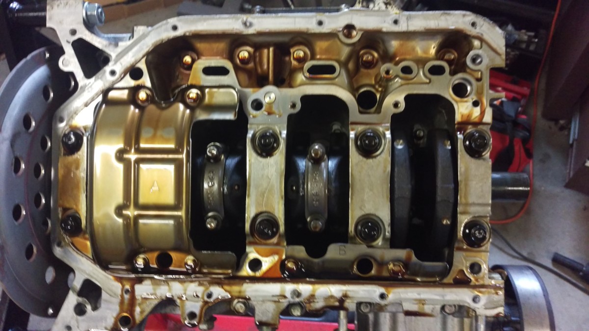
Removing the Oil Pan
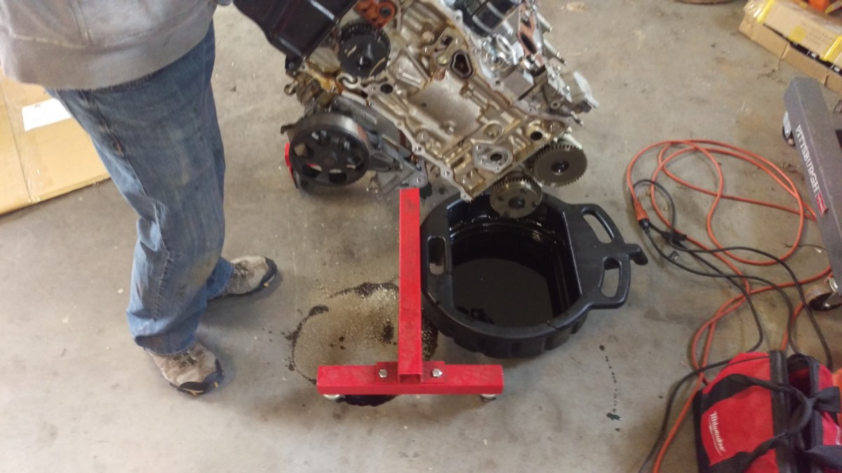
Flip the engine over on the stand
Now it’s time to flip the engine over. I ended up removing the rear water neck after this picture was taken in order to fully rotate it.
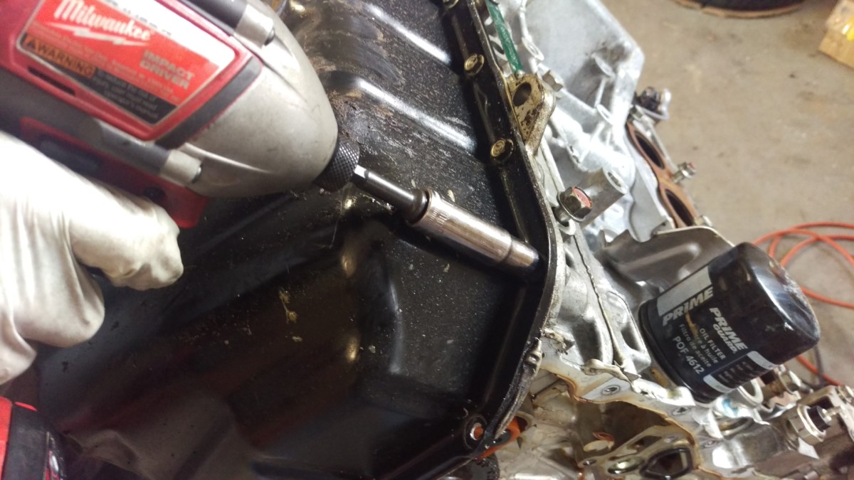
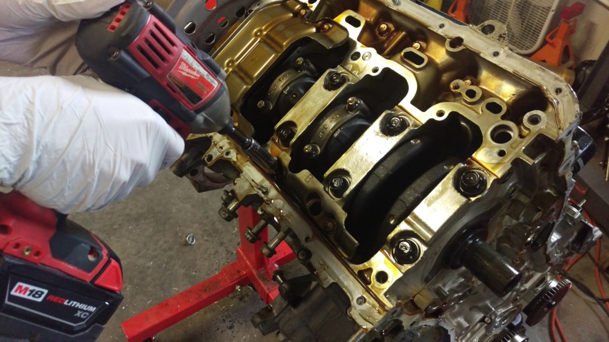
Remove all of the oil pan bolts
Now all of the oil pan bolts need to come off. They bolts have 10mm heads. An impact driver
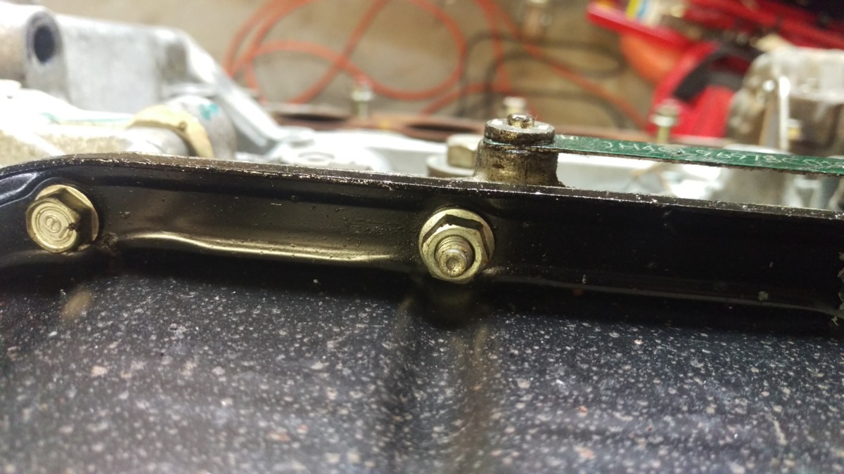
Two of them were studs, at least on my engine
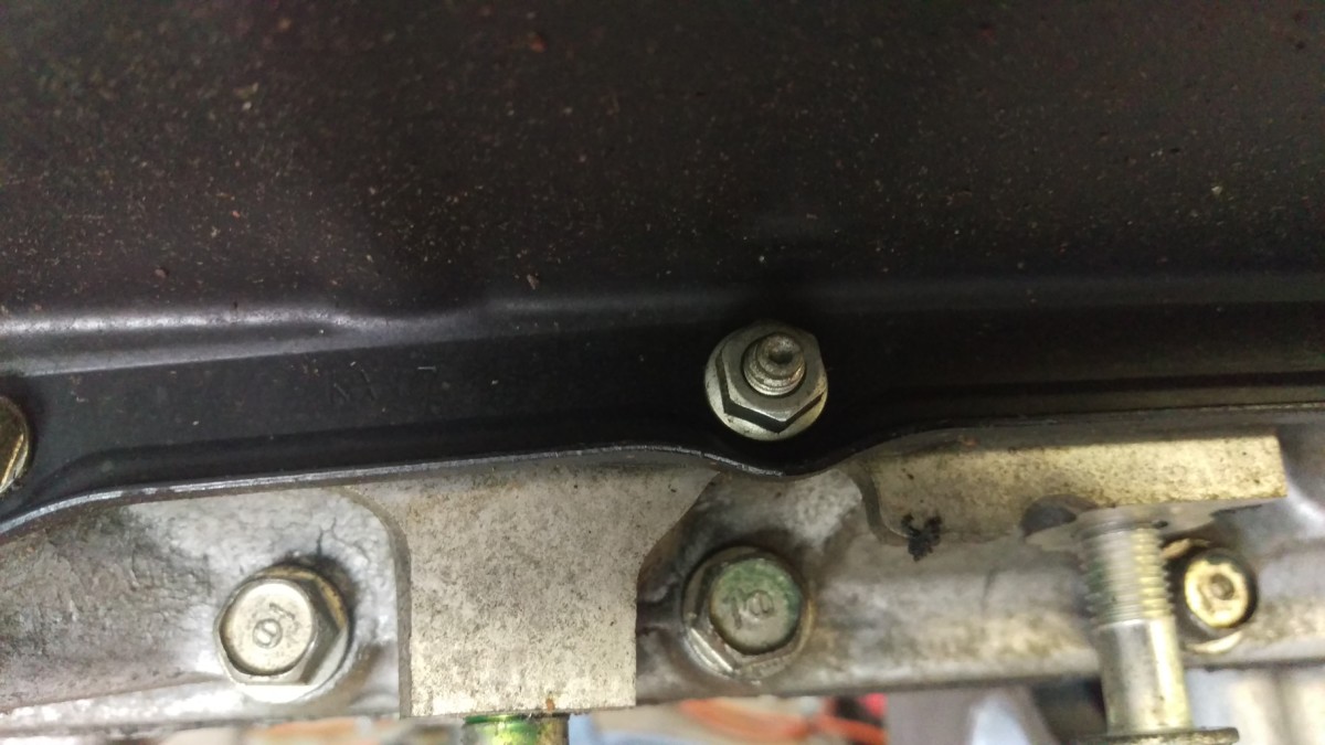
Second stud
Two of these bolts were actually studs, as shown, at least on my engine. This helps with aligning the oil pan when it goes back on.
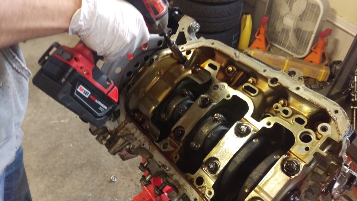
Removed
When all of the bolts are removed, you can gently pry on the oil pan off. It will be held on with RTV, like the timing cover. Be careful to not gouge the surface of the block. It doesn’t take too much force. If it does, you’ve probably missed a bolt.
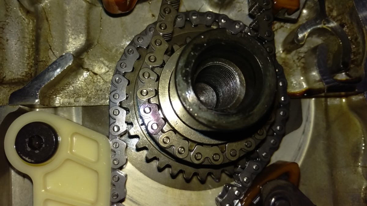
Remove the Oil Pump Chain Guides
Three bolts hold on this chain guide
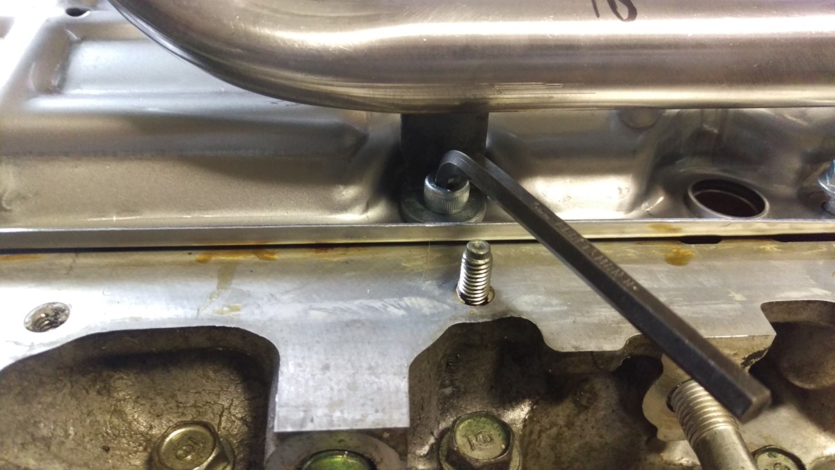
Now the chain between the oil pump and the crank can be removed. First, remove these three bolts to free this chain guide.
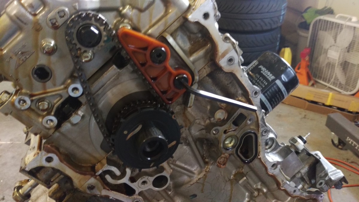
Remove the other guide
Then, go ahead and remove this other guide with an allen key. Note that the timing wheel should have already been removed by this point, even though it’s shown here.
Remove the Oil Pump

Two bolts are holding the oil pump on
Next, these two bolts need to be removed. They’re holding the oil oil pump to the block.
The two black bolts in the corners to the left of the pickup tube need to be removed
I neglected to get a picture, but you also need to get the two black bolts holding the balance shafts to the block. They’re to the left of the pickup tube in the picture, on the corners of the oil pump / balance shaft assembly. They’re shown in the KMiata video here. (Link jumps to the correct time in the video.)
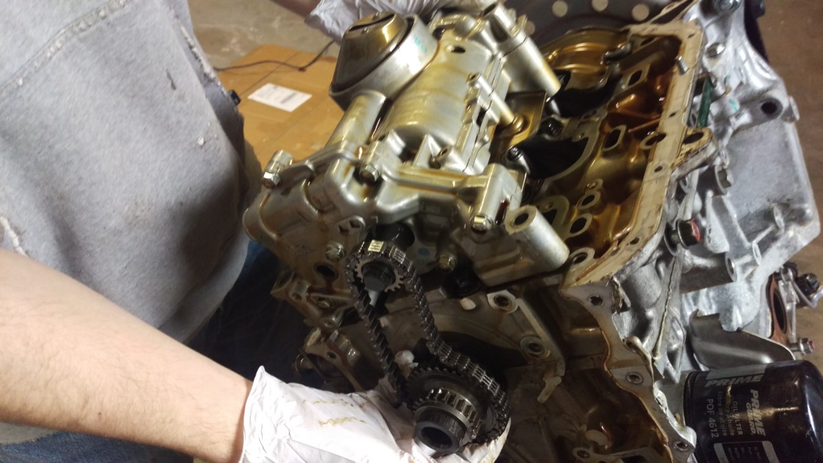
Wiggle the oil pump and gear off at the same time
Now you can wiggle the gear and oil pump off of the same time. The oil pump will slide off as the gear slips off the crank. It’s an easy procedure that shouldn’t require too much force.
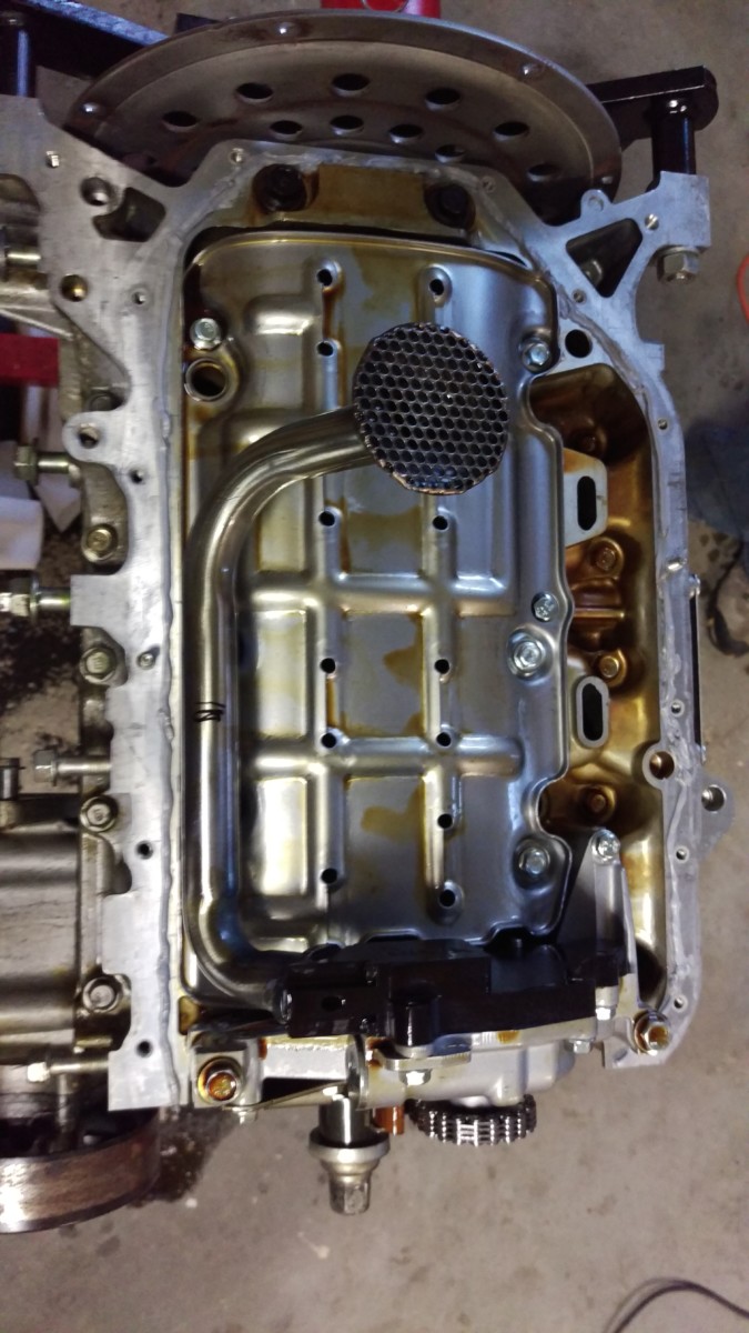
Oil pump removed
And here’s the underside of the engine with the oil pump removed.
Remove the Windage Trays
There are two bolts holding this windage tray to the block
You can now remove two windage trays from the bottom of the block. The first one only has two bolts.
The second one has four bolts
The second one has four bolts.
Assemble the New Oil Pump
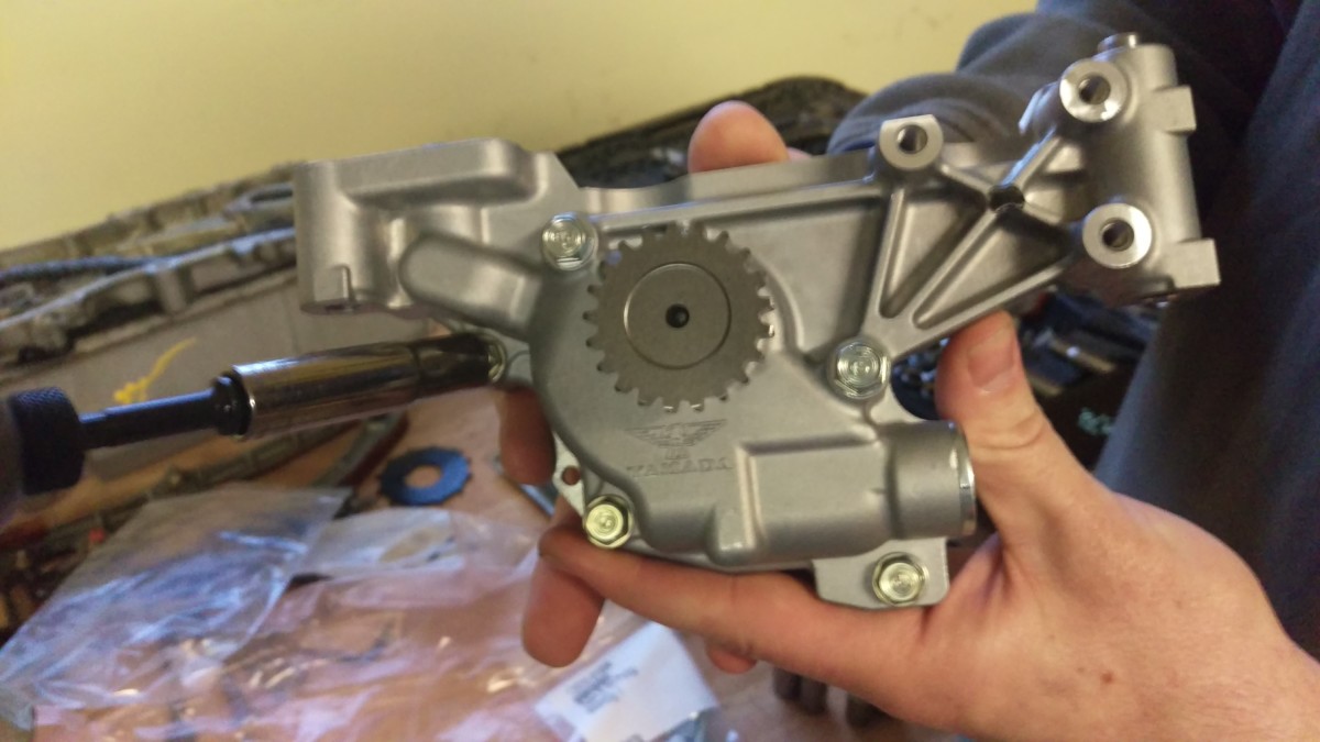
New RSX Type-S oil pump
Now is a good time to assemble the new oil pump. The KSwap uses half of an RSX Type S oil pump, shown, with a custom backing half.
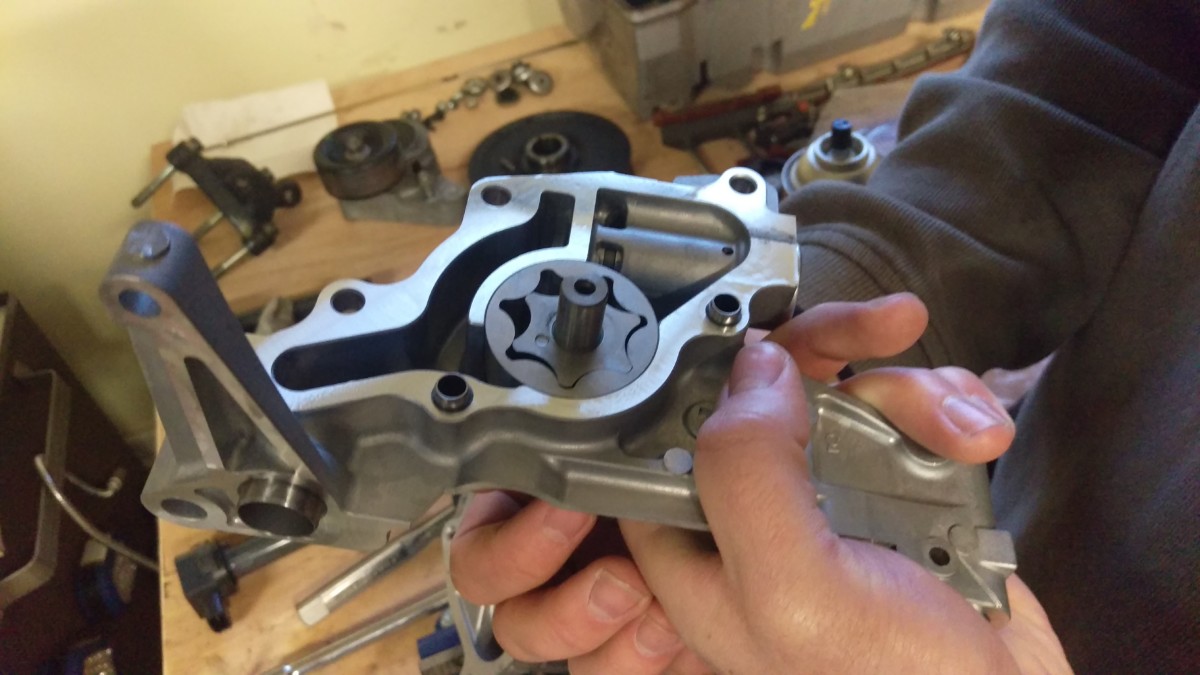
The oil pump with the back half removed
There are five bolts holding the oil pump together, all 10mm heads. Remove all of these, but keep track of where the longer bolts go.
The oil pump with the back half removed
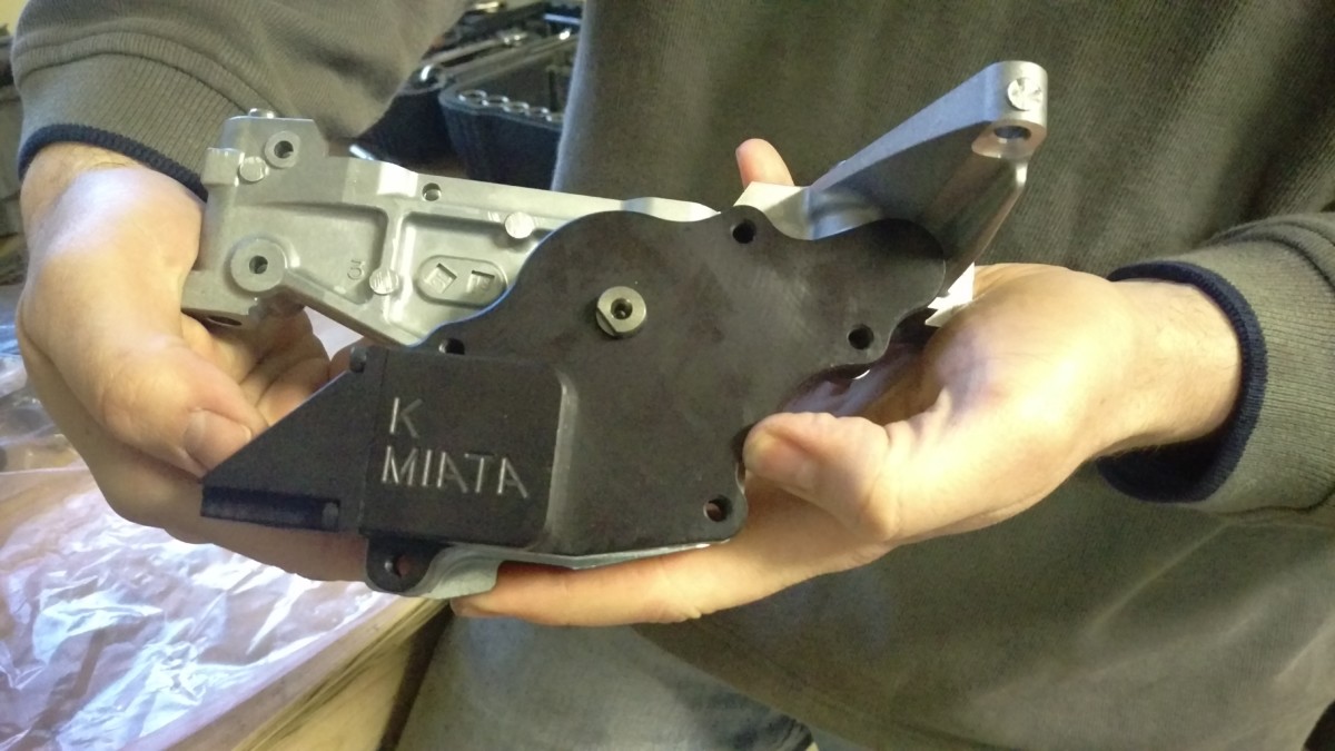
New back piece from KMiata
You can put the old back half aside. Instead, take the black anodized piece from KMiata and bolt it in its place. Make sure the mating surfaces are clean. I didn’t use any RTV or anything, as you should have two freshly machined surfaces. The torque spec for the bolts appears to be 8.7 lb-ft. I torqued them in a star pattern to 2.5, 5, 7.5, and then 10 lb-ft using a beam-style torque wrench
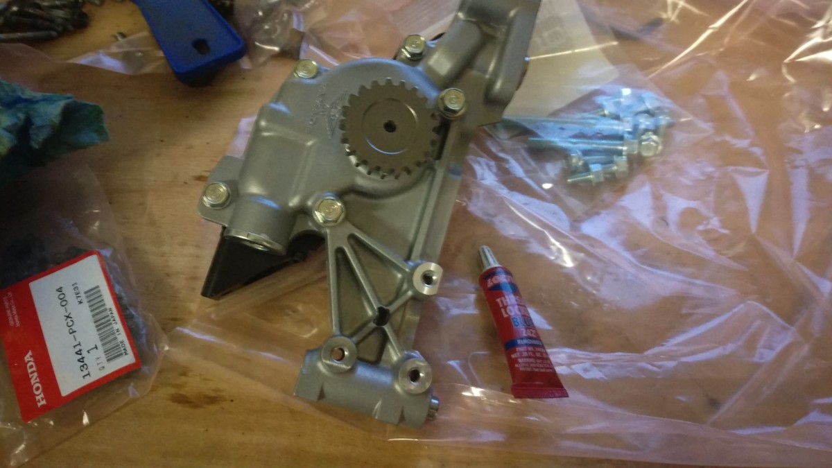
Ready for installation
I used a tiny bit of loctite blue on these bolts, as I wasn’t totally confident in the torque specs. This is probably overkill. Either way, once you have the pump put together as pictured, you’re ready to install. Also pictured is the bag of M10 bolts you’ll need for the next steps.
Remove the Oil Galley Plug and Replace with Bolt
Plug next to hole it came from
This is also better documented in the video. This oil passage bypass plug is going to be located in the block in the location shown. The guide recommends enlarging the hole with a drill, threading in a wood screw, and using vice grips to pop this out. I planned to do that, but when I drilled a hole with my 5/64″ bit, the plug popped out on its own.
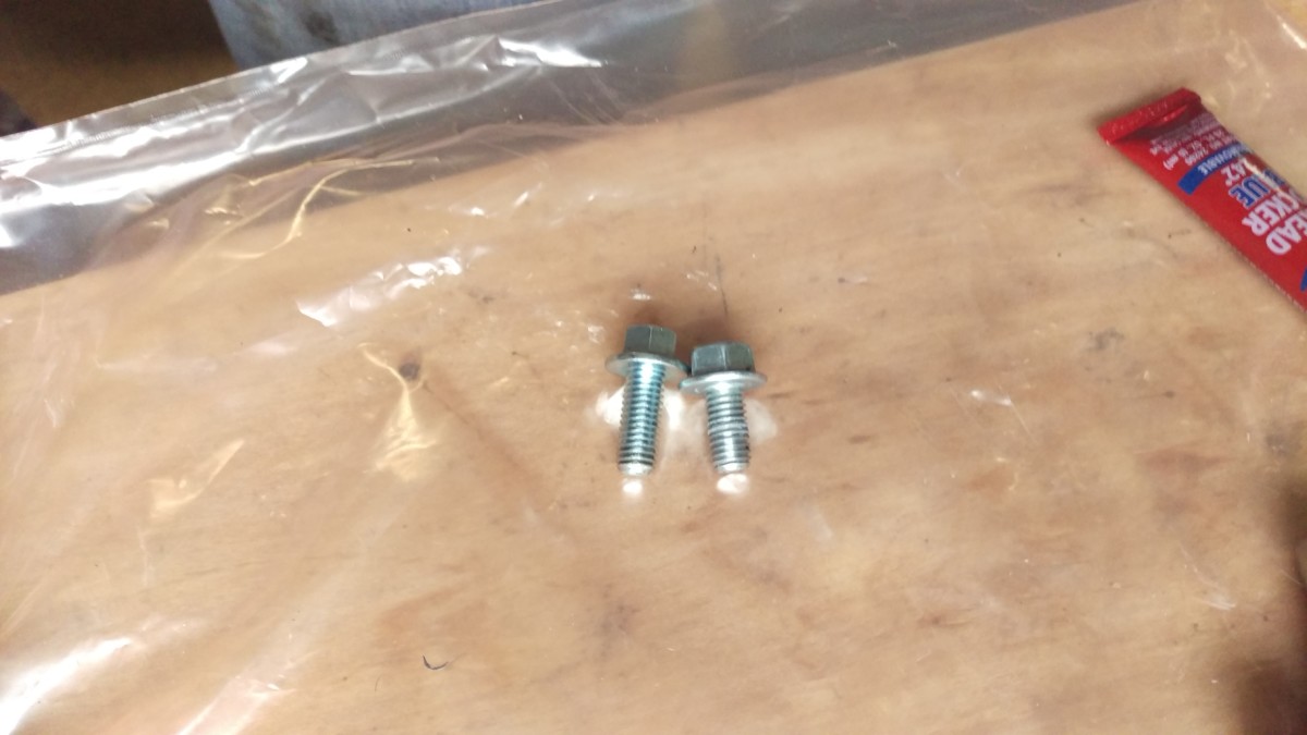
Ace (20mm) vs supplied (16mm) bolt
Once the plug is out, it needs to be replaced with a bolt to plug this hole. The kit will include an M8x1.25 16mm long flange head bolt. Unfortunately, in my block at least, this could only grab one or two threads in the block. With the application of a little bit of RTV, it got cross threaded, and I wrecked that first thread or two.
To make a long story short, I went out and grabbed a flange head M8x1.25 bolt from Ace Hardware, but got one that was 20mm long. The extra 4mm had plenty of thread to grab, and there were no further issues. I provided this as feedback to KMiata, and it sounds like they may switch to a longer bolt in future kits.
Whichever way you do this, the bolt needs RTV when installed to seal it. The way I did it was to put a small amount of blue loctite on the tip of the bolt and some RTV near the bottom/middle. I installed the bolt by hand and then torqued to 16 lb-ft. My thought process was that the loctite itself would both help seal the passage and ensure this bolt wouldn’t back out and rattle around the engine, while the RTV higher up would provide some extra seal.
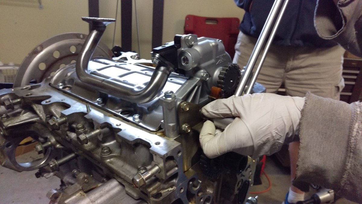
Install New Windage Tray, Oil Pump, and Pickup Tube
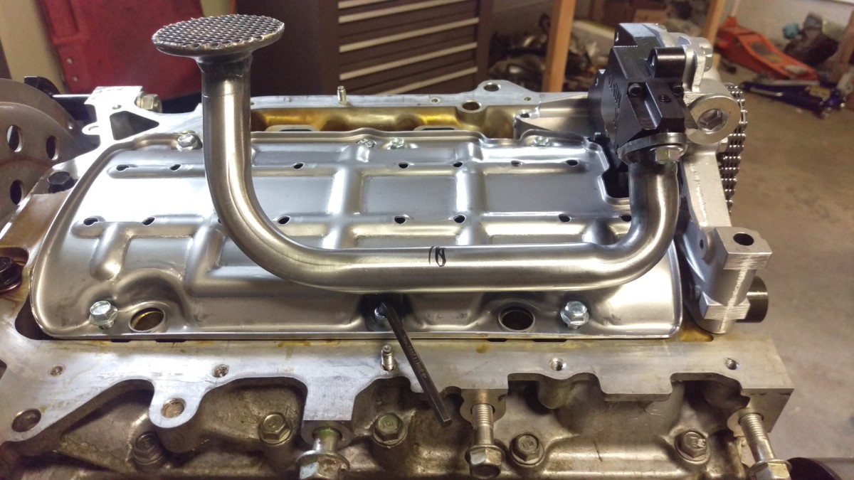
Loose assembly without torquing bolts yet
I didn’t get very good pictures of this part, but it is well documented in the video. The oil pump includes a package of bolts from KMiata. Here’s how they break down: One m8x1.25 bolt is for sealing the oil passage above. Seven of them are of the correct size to bolt down the windage tray, as well as bolt the pickup tube to the oil pump. You only need six of these bolts to do this – they give you an extra, do not freak out. There is also an allen-key head bolt for the bottom center windage tray hole, to get around the oil pickup tube. Lastly, there are three new longer bolts to secure the oil pump.
The next step is to install the new windage tray, the thin aluminum tray that comes in the kit. It bolts into six bolt holes in the block. At this point, lay the windage tray on the engine and loosely install five of the new hex bolts, leaving the bottom (intake side / left side in the picture) center bolt alone.
Then, put the oil pump, timing gear, and new timing chain in place. The new timing chain is a different length than the old one, so be sure to use it. This is the reverse operation from when you removed the old pump. Use the final of the six or seven windage tray bolts to loosely bolt the new oil pickup tube to the oil pump. Next, use the hex bolt through the pick up tube and windage tray into the block. Nothing has been torqued yet.
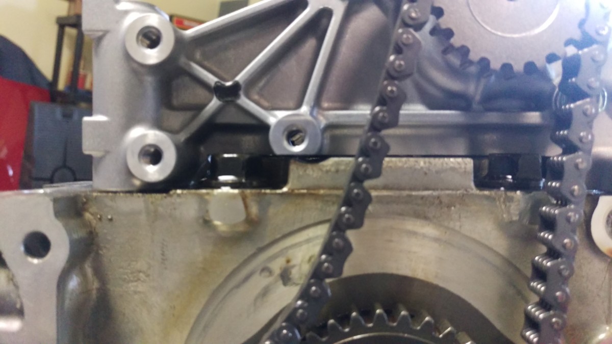
Slight gap between oil pump and block

Two bolt locations to hold the oil pump

After torquing evenly, the pump is now seated
With everything still loose, you can add two of the new longer bolts to the locations indicated in the picture. You’ll notice that the oil pump does not yet seat to the block. Torque the two larger bolts to 16 lb-ft, snugging them each down in steps to ensure the oil pan evenly mates to the block. The pump should now be flush with the block as shown.
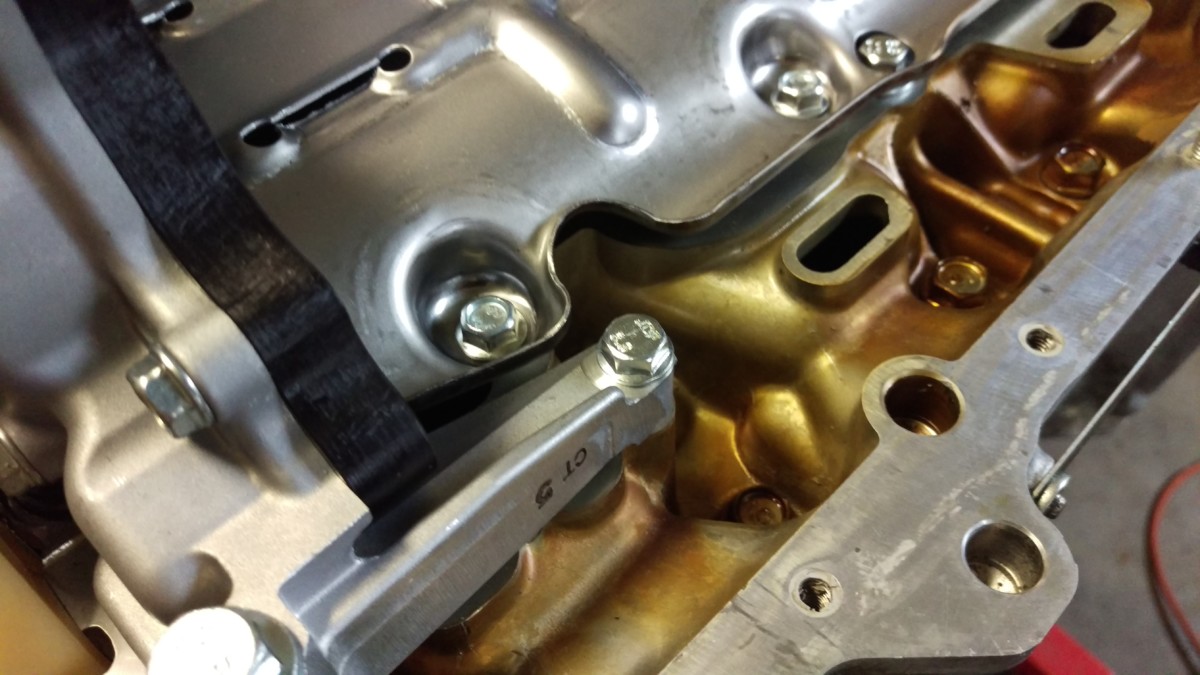
Third bolt for oil pump goes back here
The third long bolt for the oil pump goes back here. It is a smaller bolt and only torques to 8.7 lb-ft. This should use all of the bolts in the oil pump packet, excluding one extra M6.
Cut off allen wrench tightening bolt
Perspective shot
You can now torque down the remaining bolts. All of the smaller bolts for the windage tray and pickup tube should be torqued to 8.7 lb-ft. I used a torque wrench on most of these bolts, but it wouldn’t fit on either of the two bolts going into the windage tray under the pickup tube. I just got these “comfortably snug”.
For the allen key bolt, pictured, I had to use an angle grinder
Installing the Oil Pump Chain Guide and Tensioner
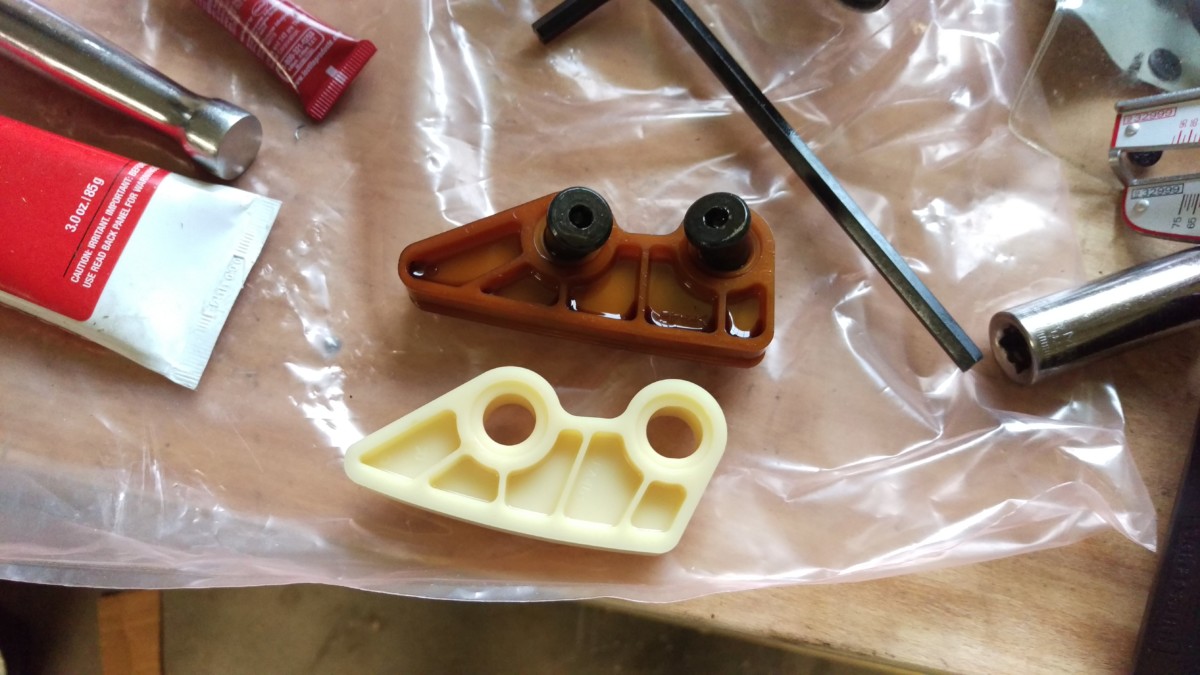
Old guide on top vs new guide on bottom
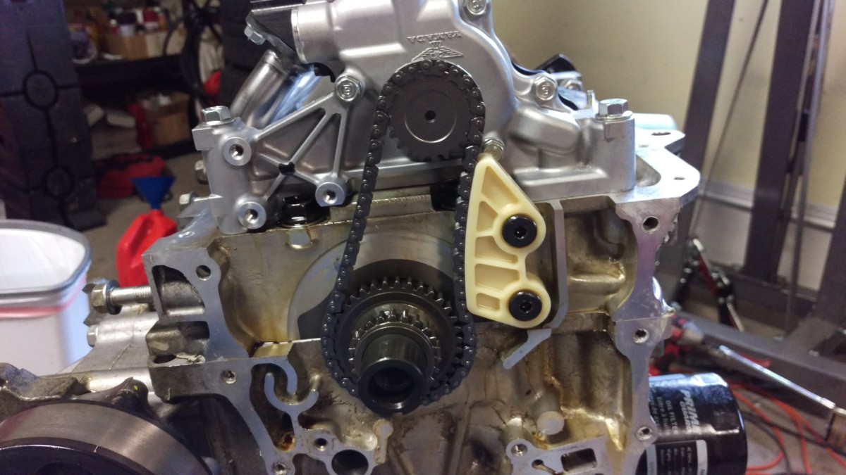
New guide installed
Now you can install the new oil pump chain guide and old tensioner. The new chain guide will be a nice white plastic, instead of the old crusty orange. This installs the exact same way as it was removed. You’re supposed to torque these, and if you have a set of allen sockets for your torque wrench, good on you. I just used a regular allen wrench and got them comfortably snug.
Guide / tensioner is reinstalled with the same three bolts
Done
The old oil pump timing chain tensioner is reused. Simply reinstall with the three bolts that were taken out when you removed it. The torque spec is also 8.7 lb-ft, as it appears to be for any bolt of this size on this engine.
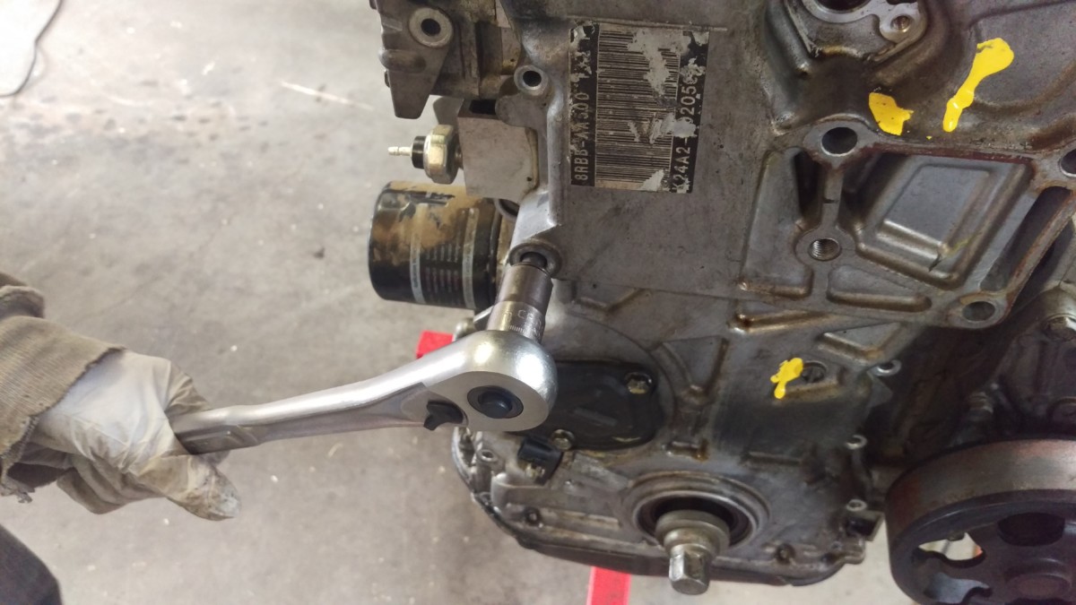
Replace the Intake Cam Gear
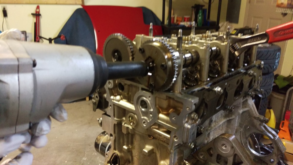
Breaking the old cam gear loose
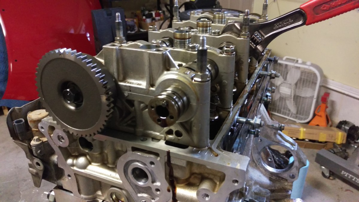
Intake cam with gear removed
This is as good of a time as any to replace the intake cam gear. The KMiata kit includes a 50-degree gear to replace the stock 25, which will significantly improve midrange torque. Replacing this gear is an easy process. First, get a crescent wrench on one of the hex flats on the cam, as pictured. Then, using either a torque wrench or a breaker bar, hold the cam still with the wrench while breaking the bolt on the front loose. I had a friend hold the wrench, and it would have helped if I had a pipe large enough to fit over the end to give extra leverage. Keep the cam shaft from spinning backwards any more than necessary while doing this. Once the bolt is out, the old cam will slide right off.
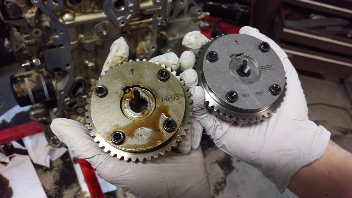
Old vs new
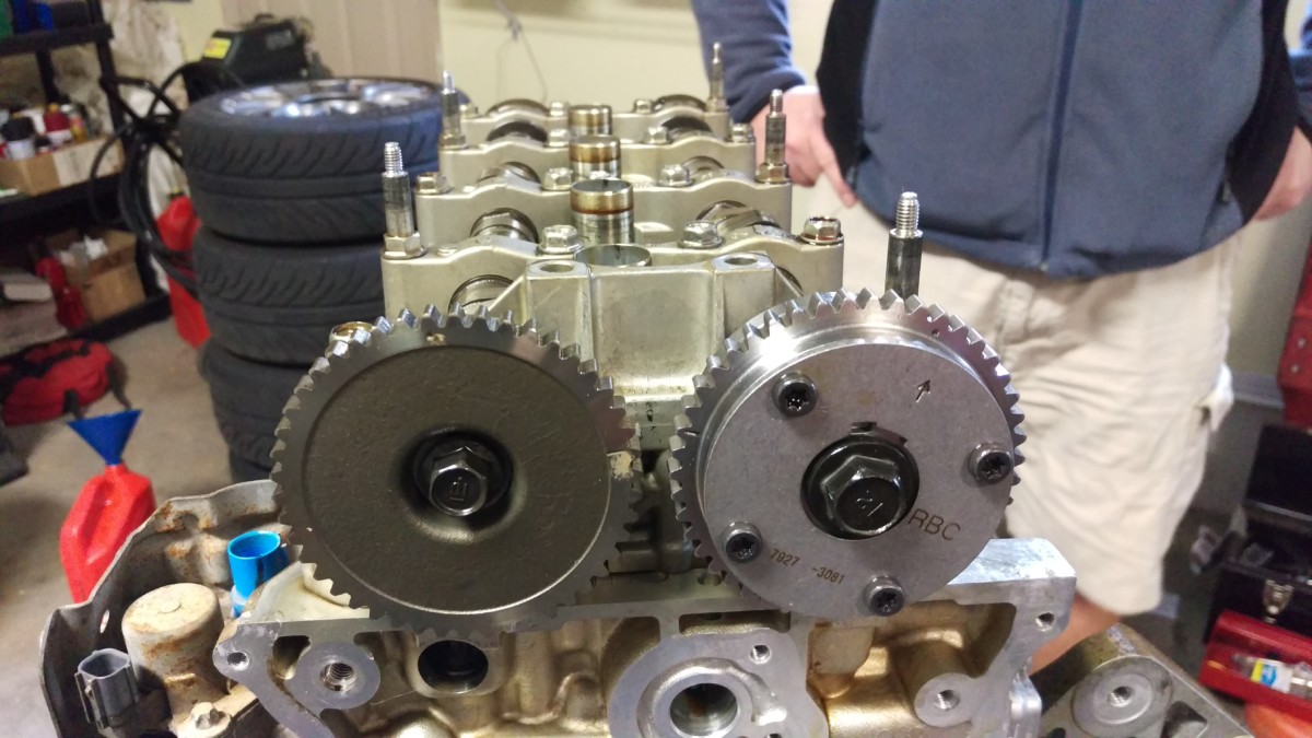
After reinstallation
Here’s the old cam gear versus the shiny new one. The cam itself is notched, so the gears can only fully seat one way, ensuring it will be oriented correctly. Make sure it’s fully seated. Keep the wrench on one of the hex portions on the cam shaft and torque the cam gear bolt to 83 lb-ft.
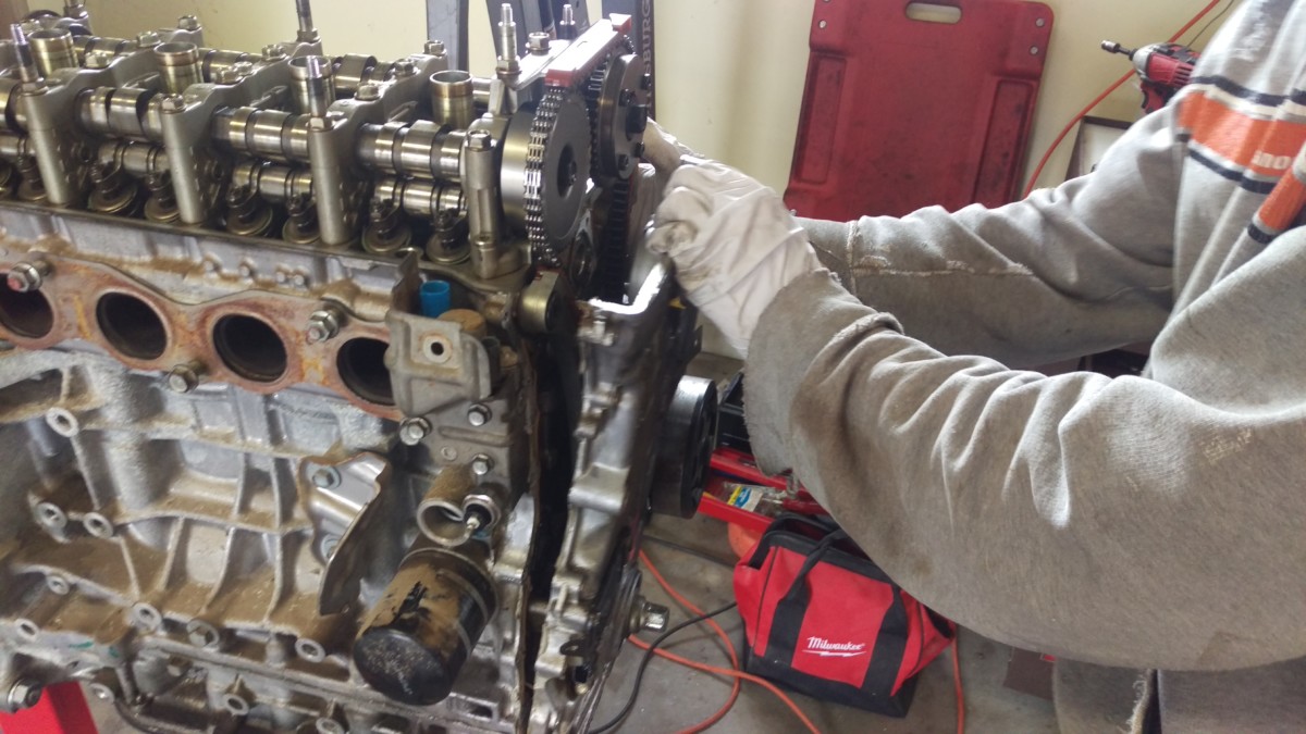
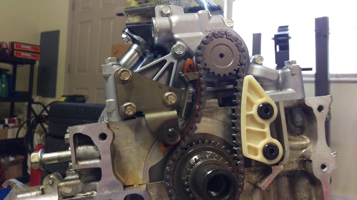
Reinstalling the Timing Chain
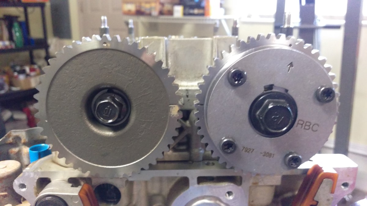
Ensure the dashes on the cam gears are facing each other
Reinstall the chain guides
Now the timing chain can be reinstalled. First, make sure the dashes on the cam gears are facing each other, as shown. The dot on each gear will point almost but not quite straight up. Depending how careful you were earlier, this may require moving them a few degrees with a wrench on the hex areas on the camshafts. Reinstall the front two timing chain guides, letting the left guide just sort of swing there for now.
Left cam with dark link
Right cam dark link
Dot on the timing gear, very hard to see, but right under the dark link
The front side of the chain will have three sections with dark links. Two will be close together, and one will be far apart. The first two sections should straddle the dots on the cam gears. The cams may need to be rotated by a tooth or two to line up. The third section will be on the opposite end of the chain, and it corresponds to a very small dot on the tooth of the timing gear on the crank.
Ready to pull the tensioner pin (green)
Done
With the chain located correctly, the new chain tensioner supplied by KMiata goes back in place. Do not pull the pin yet. It helps to have somebody hold the chain on the gears while the tensioner is installed. Once you’re satisfied that the tensioner is bolted in with the chain links in their proper locations on the three gears, you can pull the green pin. I torqued the tensioner and guide bolts to either 10 or 16 lb-ft, 10 lb-ft for the 10mm-head bolts and 16 for the larger bolts. When you pull the green pin, the tensioner spring will release, and the engine should be timed.

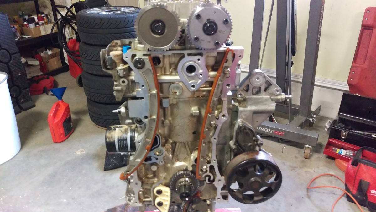
Don’t forget to reinstall the upper chain guide
Once you’ve got everything set, don’t forget to reinstall the upper chain guide. At this point, I temporarily reinstalled the crank bolt just to spin the engine a few times with a wrench. A couple of full rotations confirms that everything is spinning smoothly and that the valves and pistons aren’t making contact.
Install the New Oil Pan
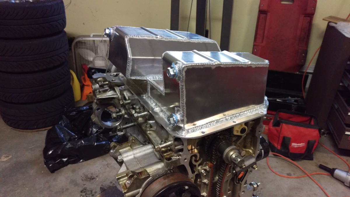
Test fit to make sure everything clears
Now is the time to do a final check on the oil pump, timing chain, cam gears, etc. Make sure all of the smaller bolts are torqued to 8.7lb-ft and the larger ones to 16. Check that no other bolts are floating around that should be reinstalled, etc. Finally, flip the engine back over and test fit the pan itself, without any RTV yet.
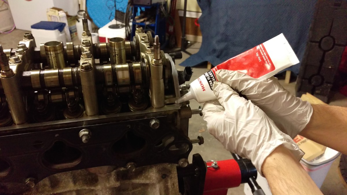
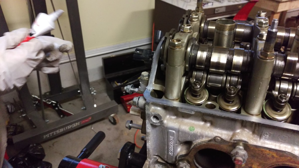
Lay a 1/4″ bead as smoothly as possible around the block
Like many Japanese engines, the K24 uses RTV instead of a manufactured gasket to seal the oil pan. Go around the block’s mating surface and scrape off any old RTV and other dirt. I like to use plastic gasket scrapers

With everything nice and clean, use the Honda Ultra Flange

Here’s how mine came out
Here’s how mine came out. Won’t win any beauty contests, but I got what I think is a reasonable amount of RTV on the inside of every valve cover hole. The Honda directions say to get the pan on within 5 minutes of putting the bead down, while the Ultra Grey and KMiata directions indicate the RTV needs some cure time. I figured that the process of laying the bead, checking to make sure I had good coverage and touch up thin spots, and installing and torquing the pan would take a few minutes by itself, so I just went immediately into installing the cover.

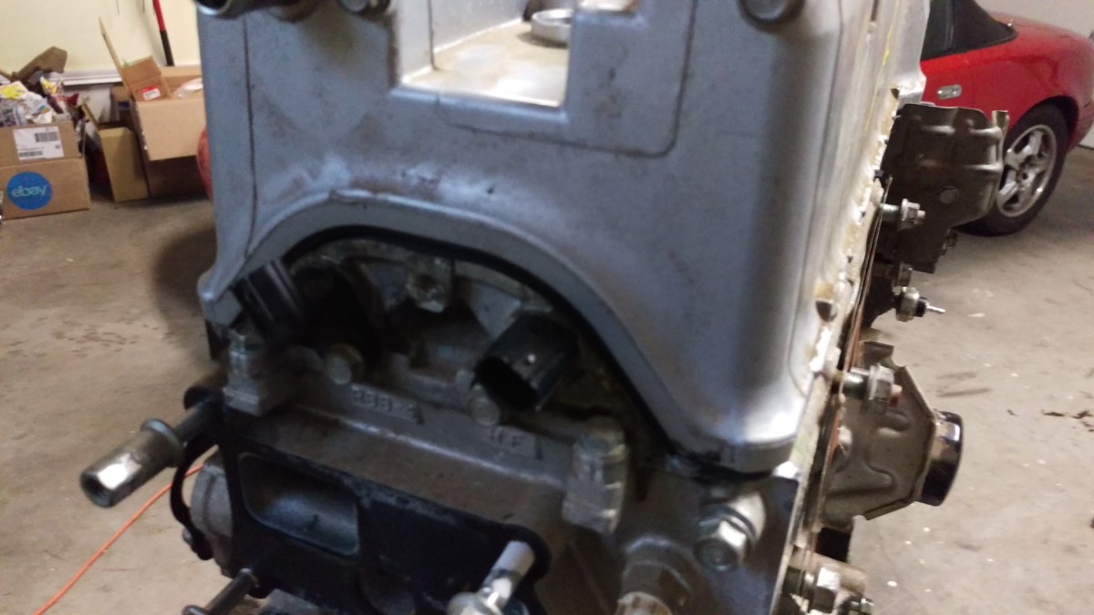
Done
Lay the pan on top, being careful not to smear the RTV. You want to get it centered and lined up before smashing it down onto the block. Then, press it straight down evenly. You want to torque the bolts inside out in a star pattern. This means doing the middle two on either side of the block, then the four outside of the middle two, and so on. I also went in stages, torquing all of the bolts and nuts to 2.5, then 5, then 7.5, and then 10 lb-ft. Meaning I went over every bolt in an inside-out pattern four times. This ensures that the oil pan will have even pressure and hopefully mate cleanly to the block without oil leaking out of any high spots. There were a couple of bolts under some of the pan protrusions that I couldn’t reach with a torque wrench, so I had to use a box wrench and guess at how tight they should be.
Reinstall the Timing Cover

Oops, I did not take good pictures for this
With the oil pan on, the timing cover can now be reinstalled. I somehow entirely skipped taking pictures for this. The procedure is just like the oil pan, however. Flip the engine back upright. Scrape the old RTV from both the cover and the block. Use some brake cleaner and a rag to make sure the mating surfaces are clean. Do not forget to clean the area around the VTC solenoid. Put a bead of Ultra Flange on the mating surface on the block, just like with the oil pan, going inside of all the bolt holes. Also put a bead around the VTC solenoid area, but go outside the final bolt. (The one that is visible in the picture, that goes through the actual solenoid.) I ignored the larger 14mm bolt for now.
Just like with the oil pan, make sure everything is set and press it in flush. Get some bolts on immediately while you hold it, since it won’t sit in place nicely like the oil pan did. Do not forget the three bolts that go into the timing cover from the oil pan. Torque all of the small bolts to 8.7 lb-ft in the same pattern as the oil pan, working from the inner bolts out. Once everything was torqued, I installed the 14mm bolt finger tight, and then came back later to torque it to about 20 lb-ft once the RTV had dried.
Reinstall the Crank Pulley

Don’t forget the woodruff key
The crank pulley should slide right back on. Don’t forget to reinstall the woodruff key with it, the small bit of metal that ensures the pulley spins with the crank.
Using holder tool
Torque to 181 lb-ft
I did this after the valve cover was reinstalled, but you may as well do it now. Use the Honda crank pulley holder

Reinstall the Valve Cover
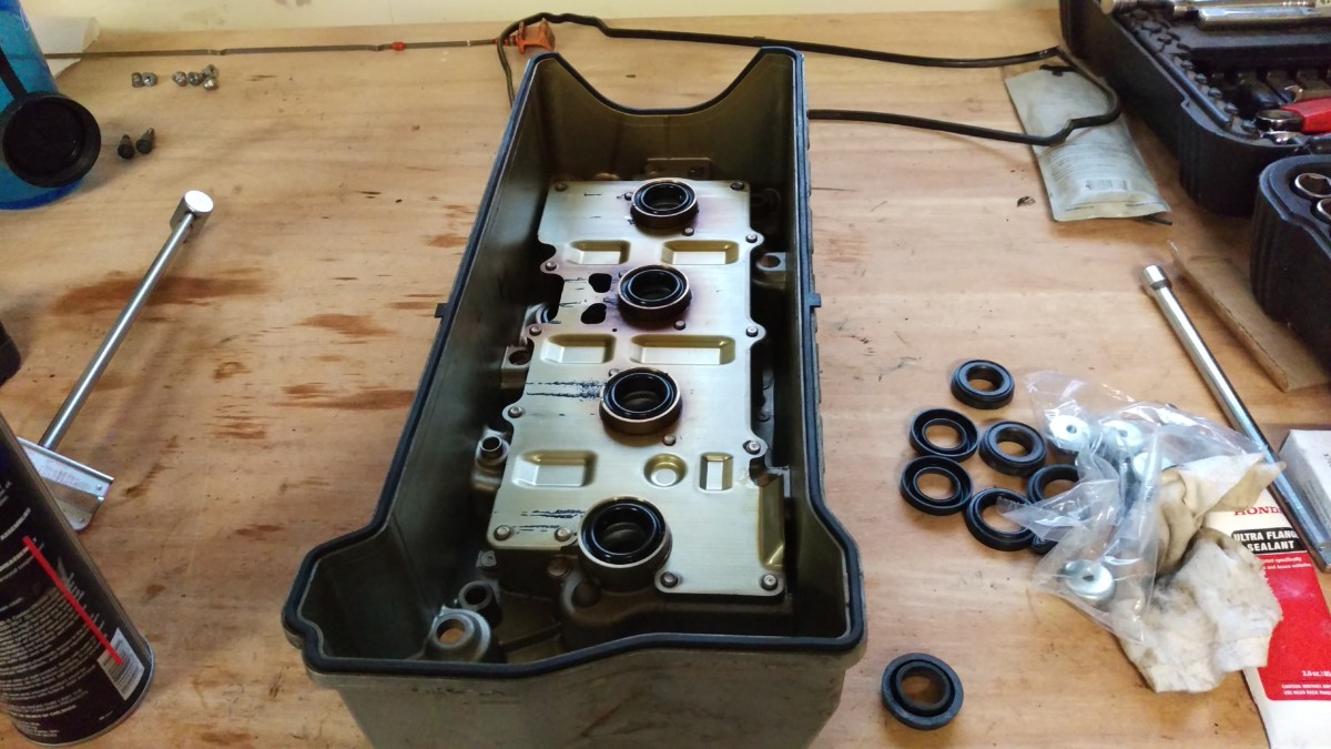
Valve cover and new gasket
It’s all downhill from here. Putting the valve cover back on is easy. I used a new Felpro valve cover gasket
Press the new gasket into the valve cover
Press the new valve cover gasket into the valve cover.
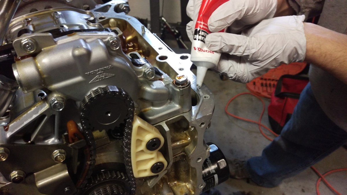
Dab RTV around this arch
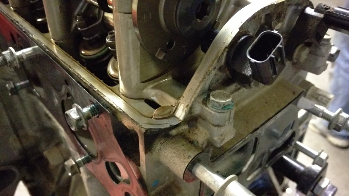
It goes in both sides
Both sides of this semicircle on the cylinder head need a dab of RTV. Remove any old RTV first, then apply a pea-sized amount.
Dab of RTV
Here’s about how much to add
Here’s another shot showing about how much to put on.
Set down the valve cover evenly
Set the valve cover down on top evenly, making sure not to smear the RTV too much.
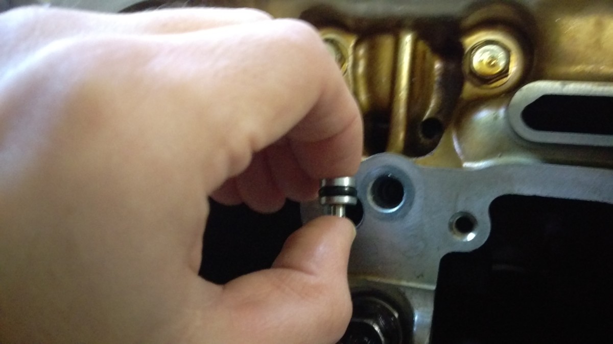
Replace the rubber seals around the studs and torque to 8.7
The new gasket should come with new little rubber/aluminum seal-washer things. These go on the studs around the valve cover to replace the old ones. Once that’s done, reinstall the valve cover nuts and torque to 8.7 lb-ft in an inside-out pattern that is probably now becoming familiar. I’ve also seen the torque spec as 7.8 or so for these nuts, but I doubt a foot pound either way is too critical. Just be sure to torque them evenly and don’t overdo it.
Fresh Spark Plugs
Plugs and coil-on-lugs
Now you can pop in fresh plugs. I put a dab of anti-seize on the threads before installing and torque to 17 lb-ft. The coil-on-plug assemblies push right on, and I just snug the bolt down. It doesn’t take much to hold it in place.
Finished
Done
And there you have it! K24A2 engine internals prep is now complete. You still need to do the coolant reroute, trim the dipstick, figure out sensors, etc, but that will be the subject of a part 2 to this series of articles.
For more instructions, see all K24 swap articles: K24 Miata Swap Main Page