Miata Control Arm Bushing Replacement
Update: Since doing this, I discovered that these polyurethane bushings were freezing up my rear upper control arms pretty badly. If you already installed polyurethane bushings or want to go with polyurethane anyway, you can fix it with a kit from SadFab to add bronze inner bushings. Otherwise, I would consider replacement rubber bushings.
Update 2: SuperMiata / 949 Racing now makes a kit similar to the above as well.
While installing my new Xida coilovers, I decided to change the bushings in all 8 of my car’s control arms at the same time. In my case, I had been hearing a popping noise periodically. Having eliminated other causes, such as bad ball joints, I settled on worn out a-arm bushings and ended up replacing them with polyurethane. Fortunately, polyurethane Miata control arm bushing replacement can be done without needing access to a press. You may need a press for rubber bushings. I also added grease zerks for future maintenance, which is recommended for polyurethane bushings.
Miatas, as with most other cars, come from the factory with rubber bushings. These are softer and, as a result, have a smoother ride. Polyurethane is a harder material. It results in better handling but a firmer ride. An added bonus is that most polyurethane bushings come in two pieces, making them easier to install than other types. For even stiffer suspension, you could look at delrin bushings.
Items Required
- Front polyurethane bushings
- Rear polyurethane bushings
- Balljoint Press
– You can rent this from Autozone’s Loan-a-Tool program for free
- Assorted 1/4″ grease zerks
- 1/4″-28 Thread Tap
- A Balljoint Separator
– Not a pickle fork, this kind works much better and can be rented for free at Autozone
- Replacement ball joint boots
– You may want these if your boots are torn or you tear them removing the UCAs


Before You Begin: Check Bushings
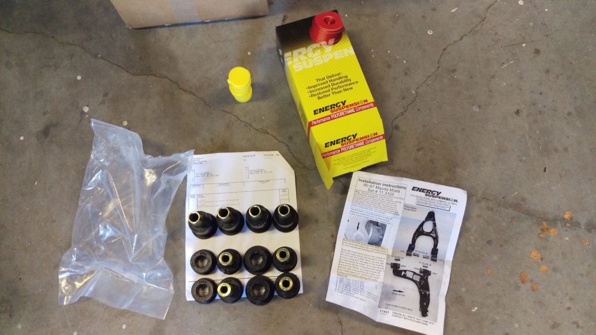
Front control arm bushings
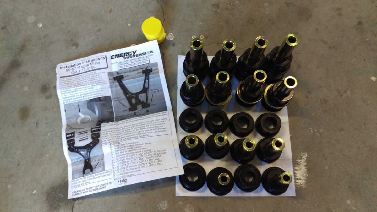
Rear control arm bushings
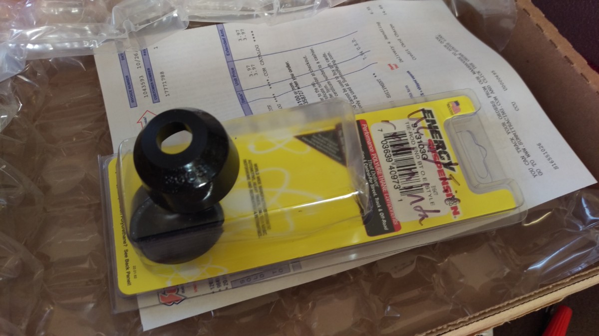
Before you begin, you should check to make sure you have all of the bushings you’ll need. If you ordered Energy Suspension bushings like I did, I have been told they occasionally mess up when packing the box. There should be a sheet describing how many of which part numbers should be present in the kit. I simply laid everything out as pictured. Also be sure you received enough tubs of grease, although any quality grease can work as a substitute in a pinch.
First Step: Remove the Coilovers
The first step is to go ahead and remove the coilovers. Refer to my other article for details on how to do this. I would remove the front coilovers, then replace the front control arm bushings as described below with the front of the car still in the air. After the front is completely finished, I would move to the rear.
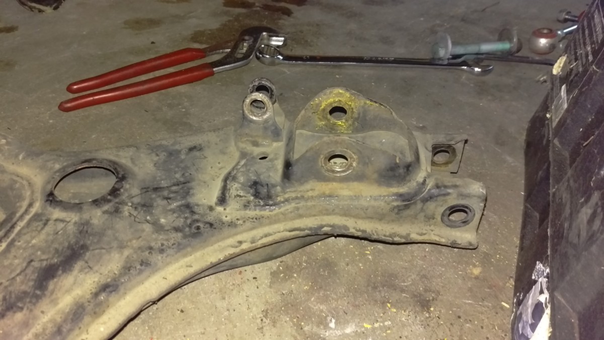
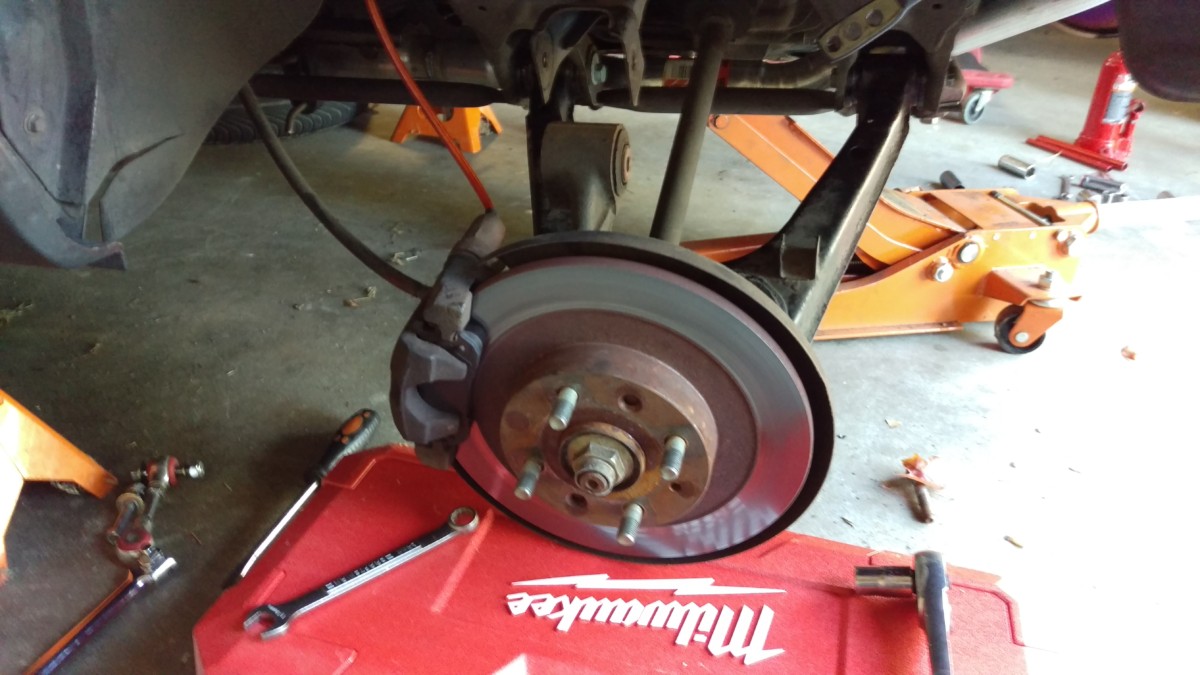
Removing the Front Lower Control Arms
Remove this bolt, the shock should be removed already
With the coilovers removed, the lower control arms come out very easily. The next step is to remove the bolt the wrench is attached to in the picture. The yellow shock, of course, should have already been removed earlier.
Second LCA to ball joint bolt
Removed
Then, you can remove this bolt and nut. With both of these bolts removed, the LCA and wheel hub should pull apart. The lower ball joint will stay attached to the wheel hub. You may need to prop the wheel hub on something at this point, depending on whether the UCA is disconnected yet. Just make sure the brake line isn’t under any strain.
Marking alignment
Marking alignment
Once the LCA is disconnected from the wheel hub, it simply needs to be detached from the subframe. First, mark the current position of the LCA eccentric bolts with a marker or paint pen. You’ll use this later to reposition the eccentric bolts. You’ll still need an alignment, but this will help keep your car driving straight on the way to the shop.

Remove the LCA Bolts
Remove the LCA Bolts
After that, you can go ahead and completely remove both LCA bolts on each side. The control arm can now be pulled free from the body of the car. You probably want something to prop up the wheel hub at this point, as mentioned earlier.
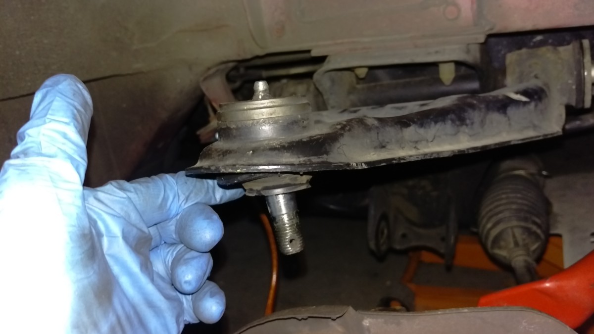
The LCA is free
And with that, the LCA should easily pull out. You can set this aside for now while you remove the upper control arms.
Removing the Front Upper Control Arms
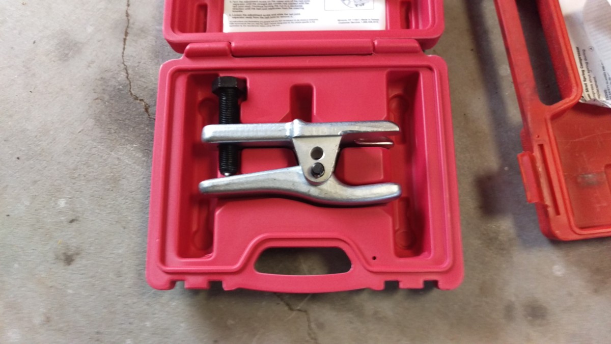
Free autozone ball joint separator rental
The upper ball joint is pressed into the upper control arm. The easiest way to remove the arm is to disconnect the ball joint from the knuckle or spindle or hub or whatever it’s called. The quickest option is the ball joint separator tool pictured. You can buy them cheaply at harbor freight or simply rent one from Autozone for free.
Replacement ball joint boots
The ball joint separator does a pretty good job separating the ball joint without tearing the boots. If you tear one or want to order ahead to play it safe, these boots are excellent quality and fit perfectly
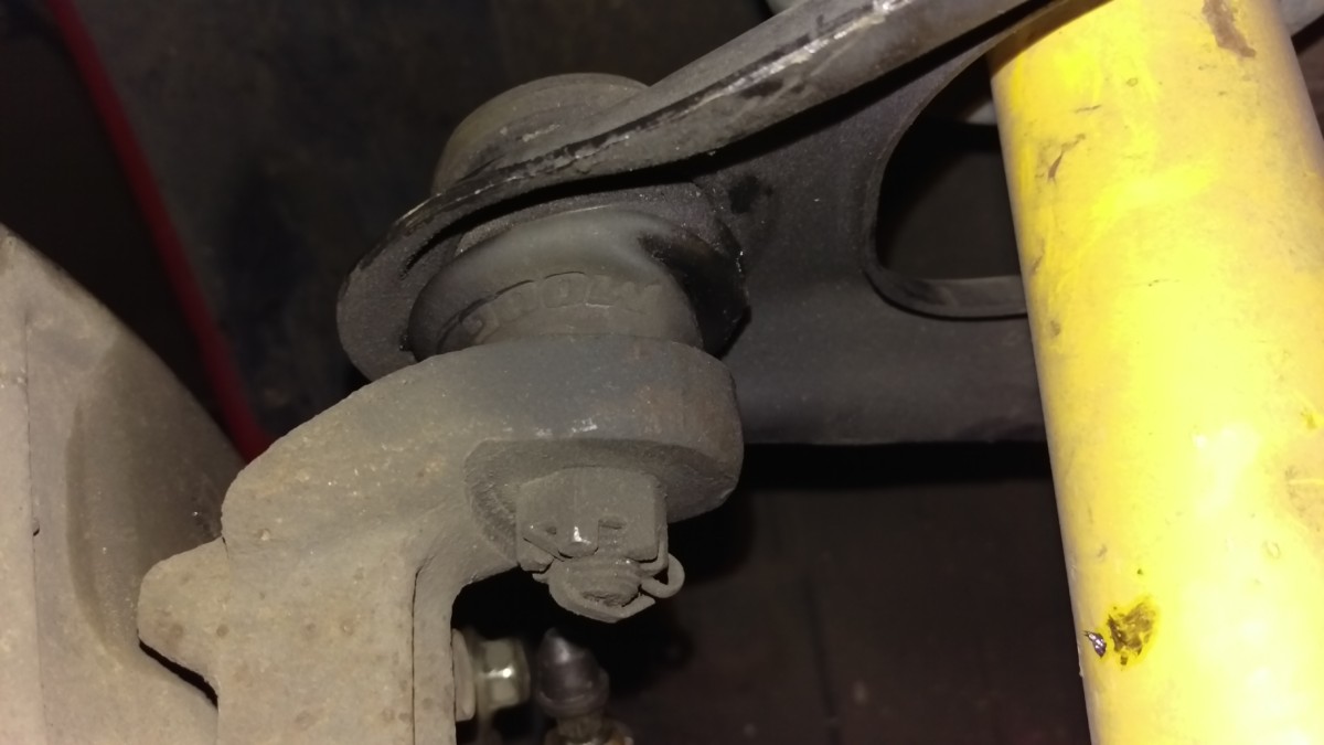
Undo the cotter pin and unbolt the upper ball joint
Cotter pin removed

The Upper Ball Joint is free to be separated apart now
To separate the UCA from the knuckle, first remove the cotter pin with a pair of pliers. Then you should be able to unbolt the castle nut. It shouldn’t be on all that tight. At this point, you are ready to use the separator.
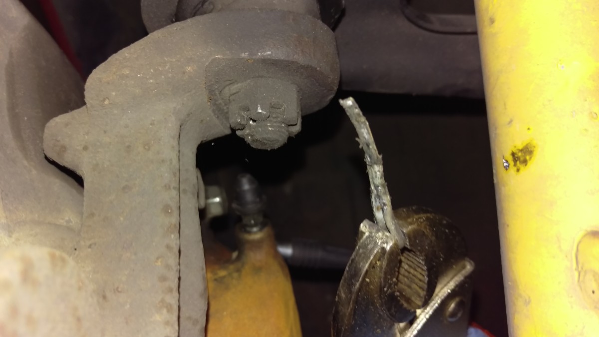
Separating the upper ball joint
The separator slides on as shown. Simply get the fork underneath the ball joint boot and then start tightening the bolt on the tool with a wrench.
Ball joint is free
The ball joint should pop right out with little fuss. This is a good opportunity to inspect this ball joint. You want the rod to be tight but move without binding. It should take a good amount of force to move it around. When these start to fail, they’ll often start to get very loose.
At this point, the wheel hub will be free to move around. Make sure it is resting on something, such as a block of wood or a ramp. You do not want to put any strain on the brake line.
Remove the long bolt with a couple of wrenches
The final step is to remove the UCA bolt. If you removed your coilovers with the long bolt method, you’ve already done this part. In a nutshell, you simply need a socket and a box wrench. Remove the nut from the bolt as pictured, and push the bolt out towards the front of the car. You may have to remove the sway bar to get it out. The Long Bolt Removal section of the coilover removal writeup has further details.

At this point, the UCA should also be free
At this point, the UCA should be free. Don’t forget to support the wheel hub on something to keep the brake line from being strained. You’re now ready to replace the bushings on the front arms.
Removing the Front Bushings
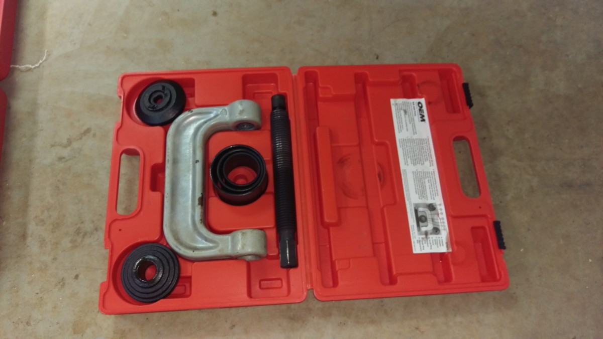
The ball joint removal tool that can be rented for free at Autozone

Ball joint adapter set that can also be rented for free
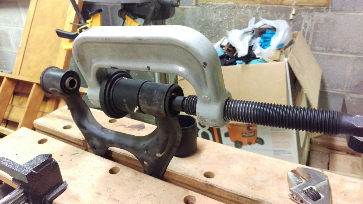
Now that you’ve got the control arms free, it’s time to pull the old bushings out. The front arms each have two bushings to remove. I have heard of people using a three jaw puller from Harbor Freight to do this, but I found it to be awkward and finicky. I much prefer to borrow the pictured ball joint separator from Autozone’s Loan-a-Tool program for free.
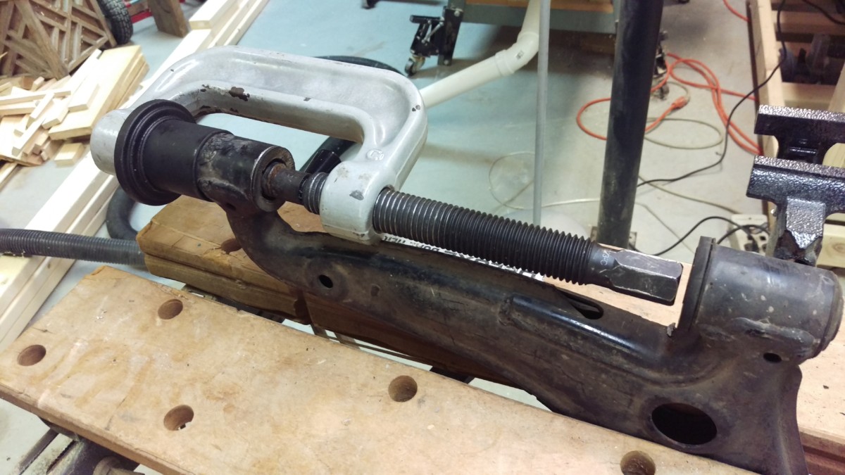
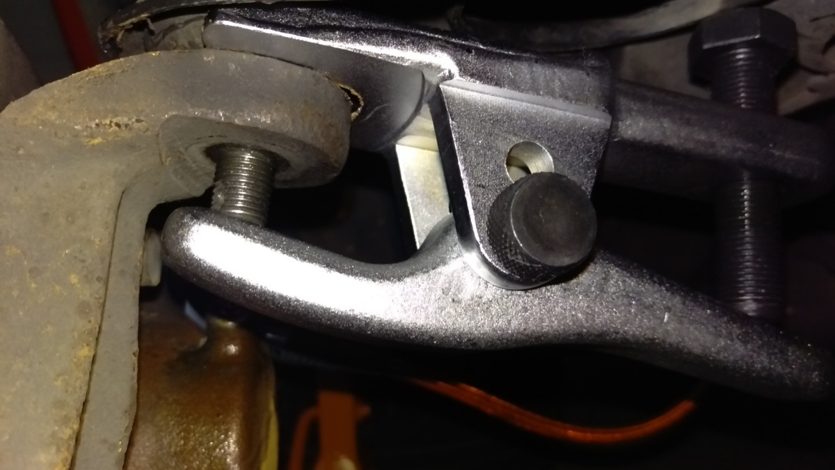
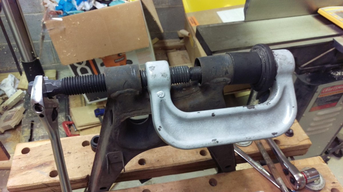
Pushing out the LCA bushings
To remove bushings with the ball joint tool, simply select the right size cup and push it out by cranking on the clamp as shown. You’ll have to turn it fairly hard with a wrench, but the bushings pop out relatively easily. The LCA bushings are the easiest because they’re so far apart.
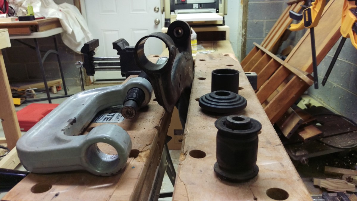
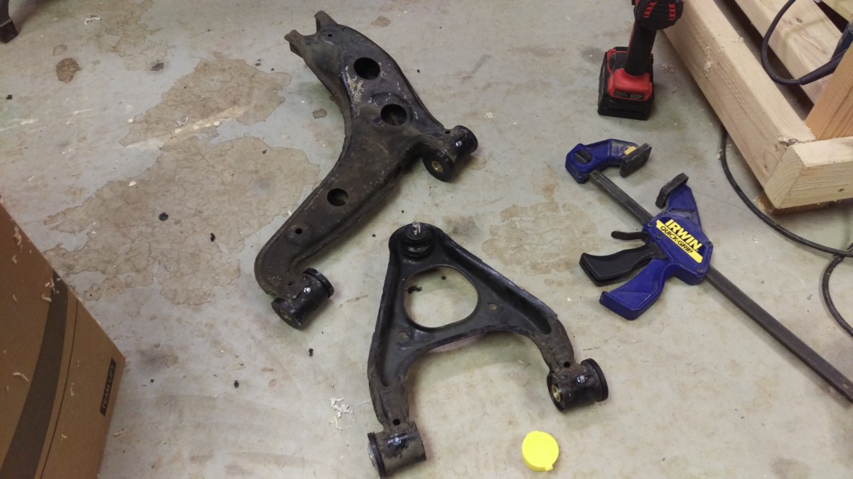
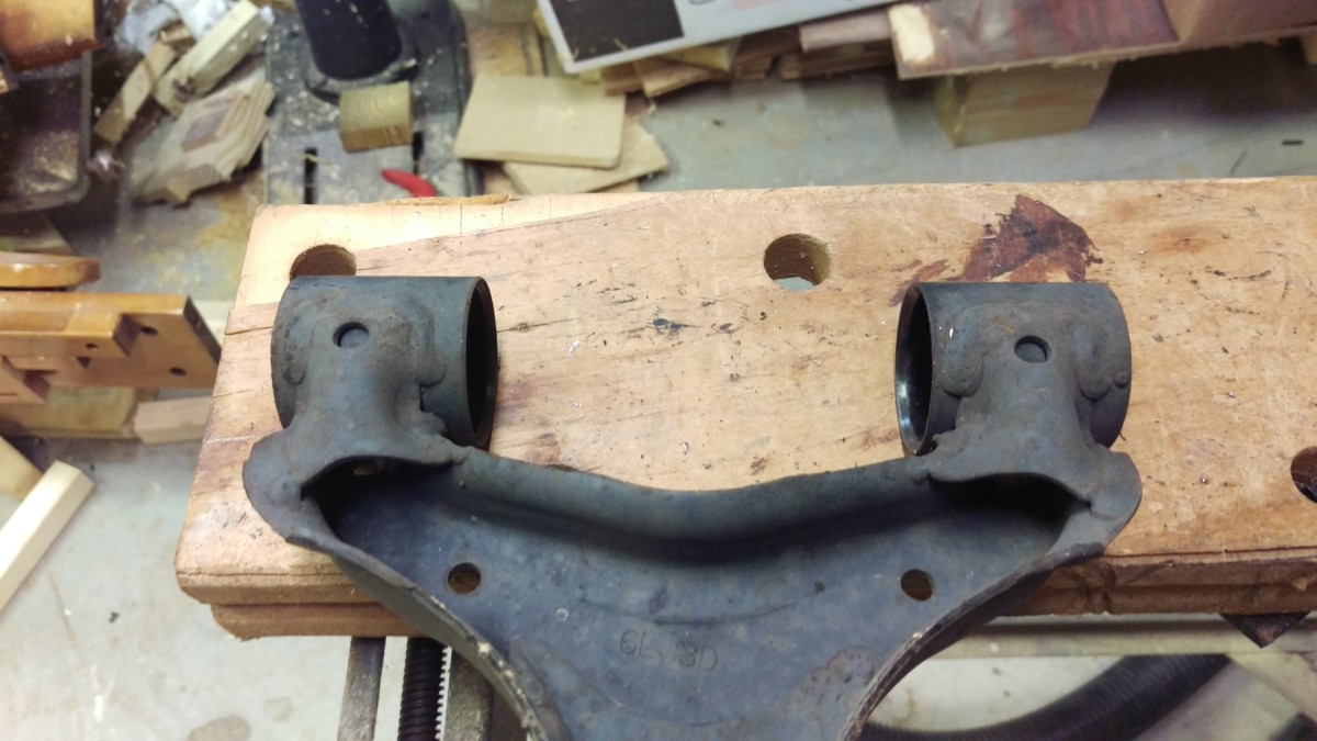
Bushings removed
Bushings removed
Here’s the same a-arm with the bushings out.
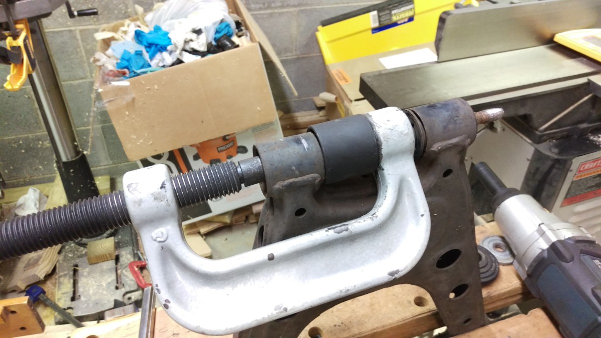
I had to get more creative with the UCA bushings
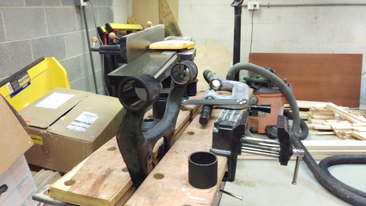
Bushings removed
The UCA bushings required a bit more creativity. I ended up simply doing the same as before, but pushing the bushing out towards the inside instead.
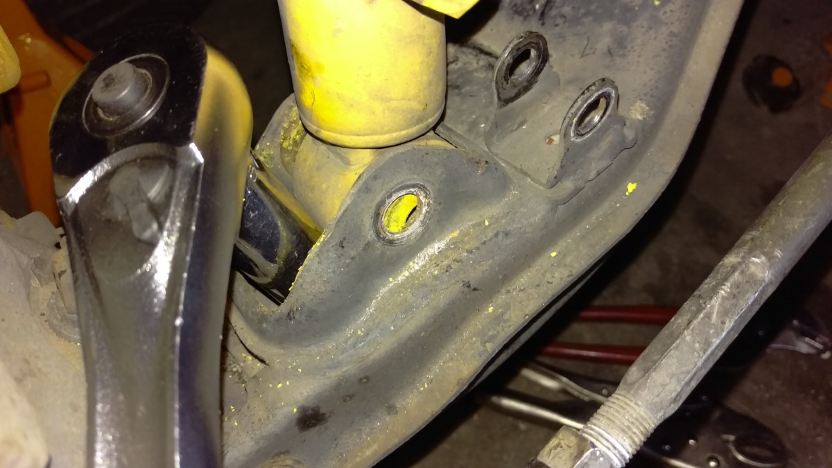
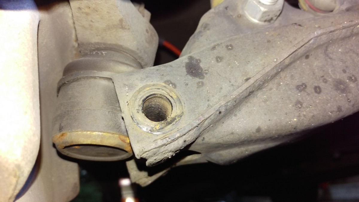
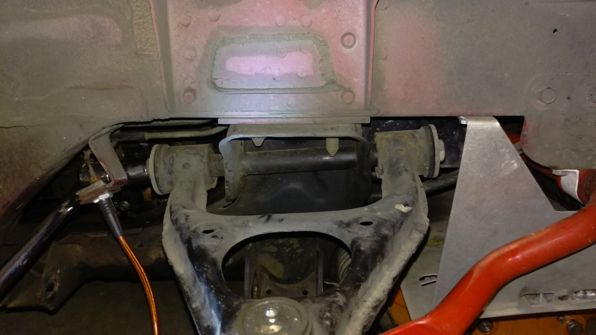
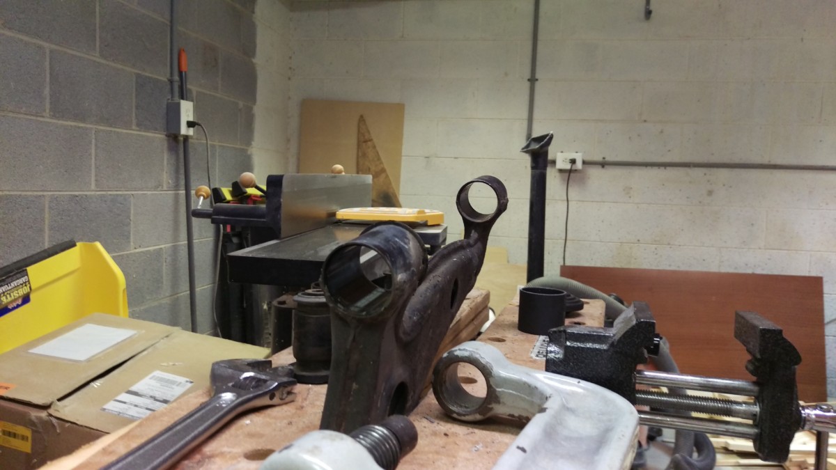
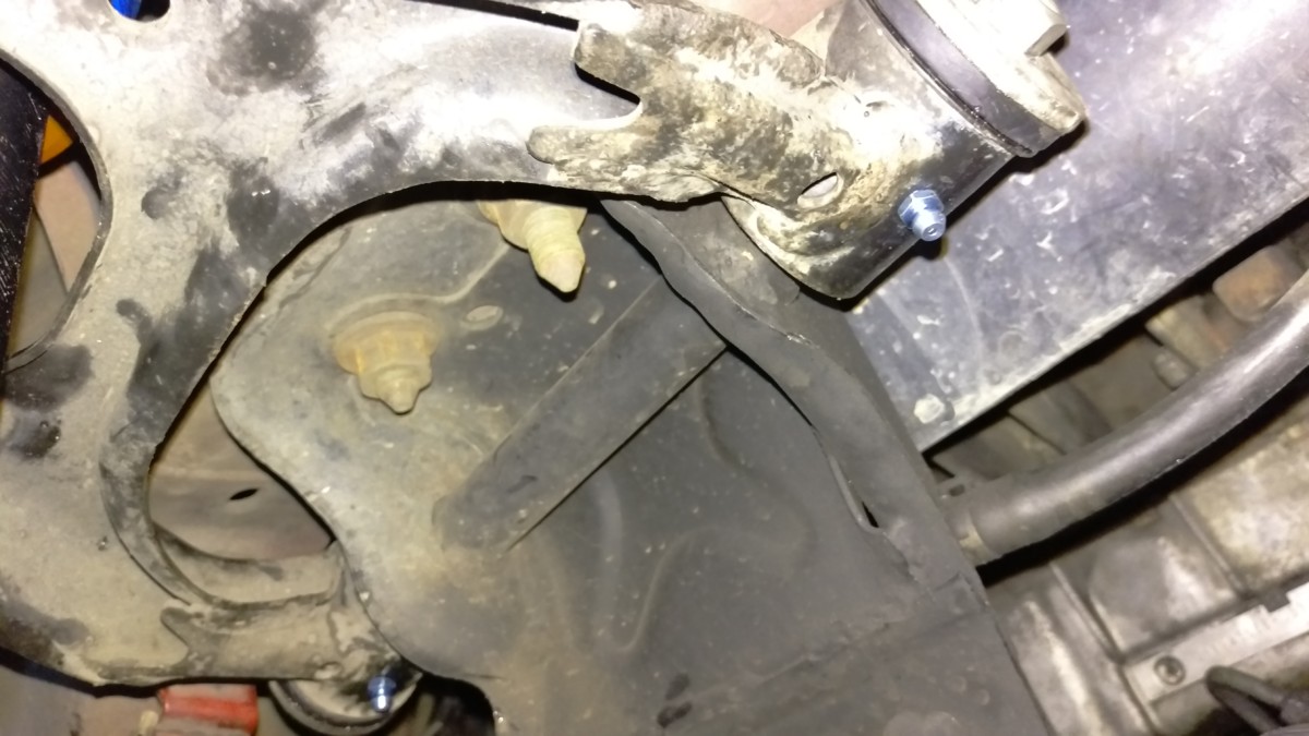
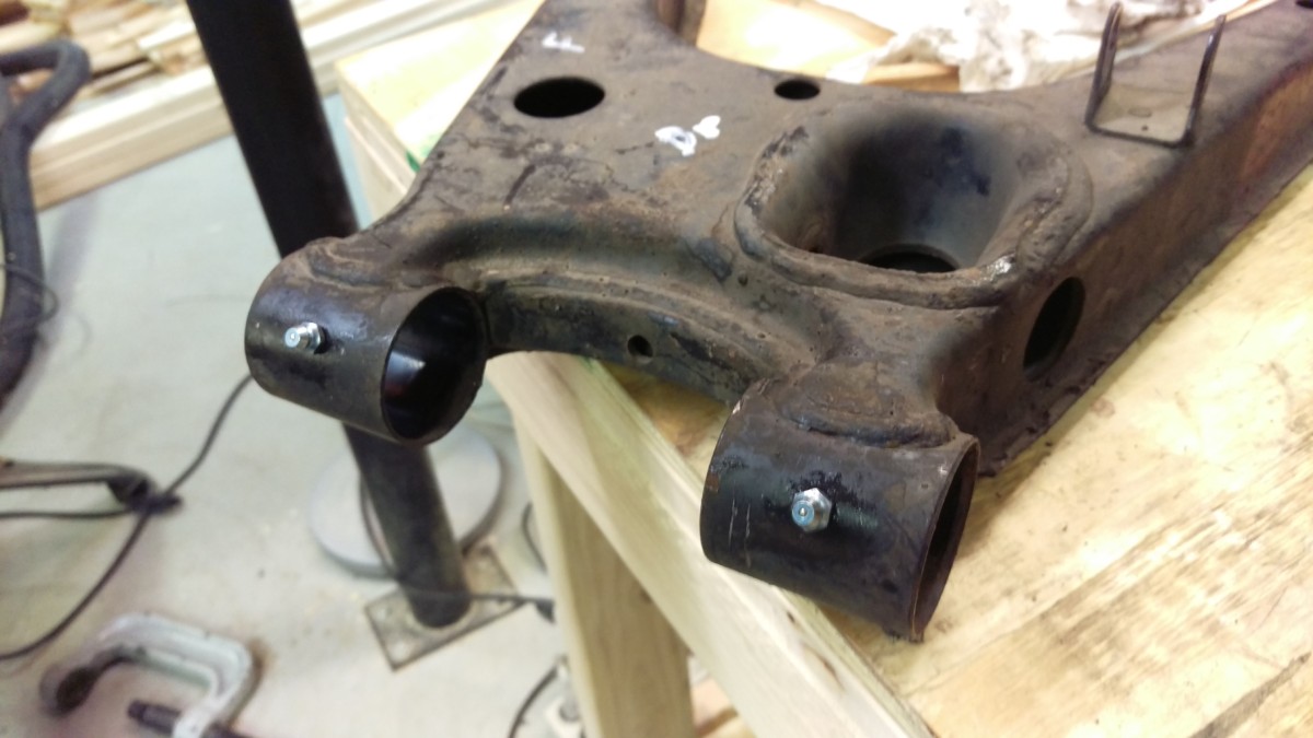
UCA Grease Zerk Locations
Grease zerk locations
Here’s a picture to illustrate where the UCA grease zerks can go. 949Racing also has images on their website. The key is to place the zerks so that they’re accessible for service while also not hitting the subframe while driving. Read on below for information on how to install the grease zerks.
Drilling and Tapping the Grease Zerks
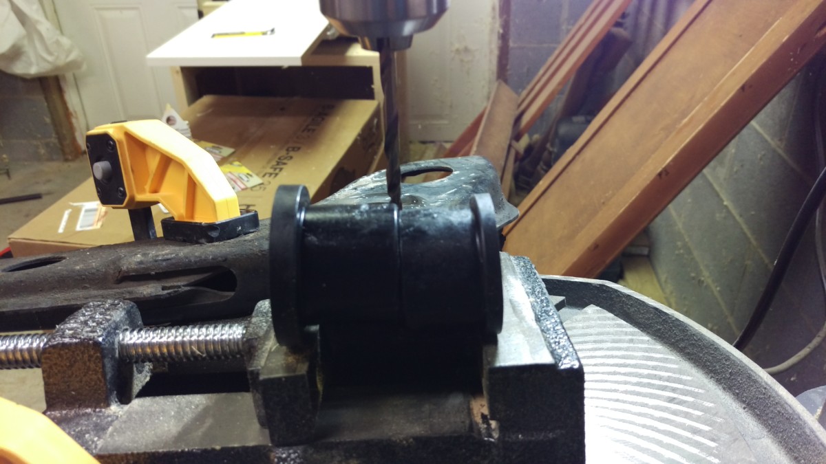
Drill for the zerk in the gap between the halves
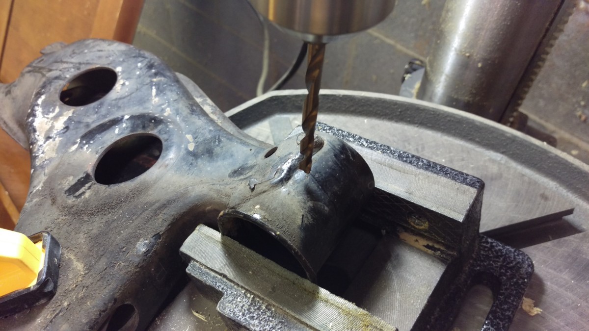
A drill press vise is handy, but you can use a hand drill
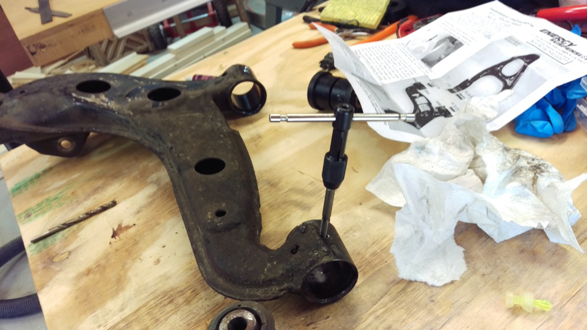
For every two-part bushing, the grease zerk should be placed where the two halves come together. The grease needs to get between the polyurethane bushing and the brass insert. Placing the zerk here allows the grease to be forced down between the bushings to where it needs to go. I simply line the bushings up to figure out where to place it. I use a center punch to make sure the drill doesn’t wander from where it needs to be. If you miss the center, you can install half of the bushing and drill a hole straight through it later on if necessary.
One piece bushings
A few of the bushings are one piece, like this one pictured. In that instance, simply drill a hole roughly centered. Then, drill a hole through the bushing before putting the zerk in. In order to not damage the threads, you may want to drill the a-arm, install the bushing with grease, drill the bushing, tap the hole, install the zerk, and then push in the brass insert.
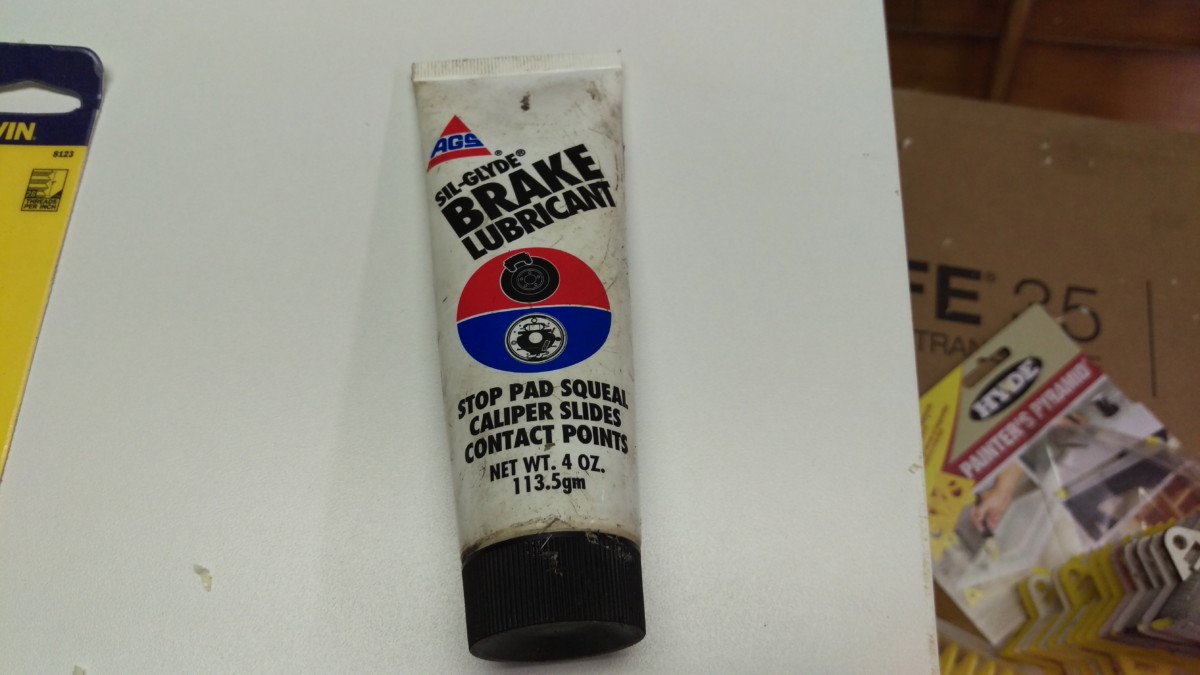
Use some kind of oil, grease, or tap compound to lubricate the drill
When drilling steel, it’s important to go slowly so you don’t overheat the bit. I set my drill press for 300rpm. You also want to make liberal use of some kind of lubricant. Motor oil works, as does some kind of grease. This time, I used this brake slider pin lube that I had handy. Lastly, having good sharp bits goes a long way. I really like the set of Milwaukee Cobalt bits I’m using in the picture so far.

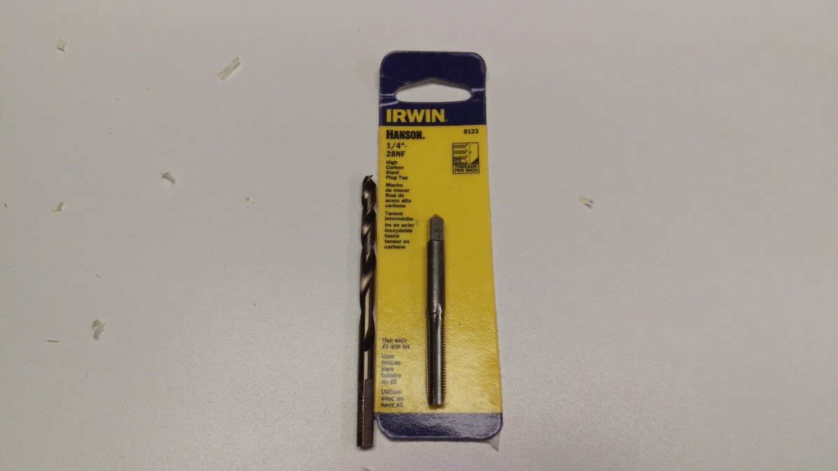
1/4″ Course Thread Tap
Tapping for the zerk
Once the holes are drilled, you can tap them. I used 1/4″ SAE grease zerks

Apply some kind of grease or tap compound liberally in the hole. Then, with the tap in a tap wrench
Afterwards, you can hose out the newly threaded holes with some brake cleaner. Also clean the inside of the bushing holes while you’re at it. At this point, the a-arms are ready for new bushings.
Installing New Bushings
When installing the bushings, check and double-check the part numbers on the diagram that came with them. The two halves will often look extremely similar, except one will have a thicker flange. You may not notice until you have trouble installing them later on.
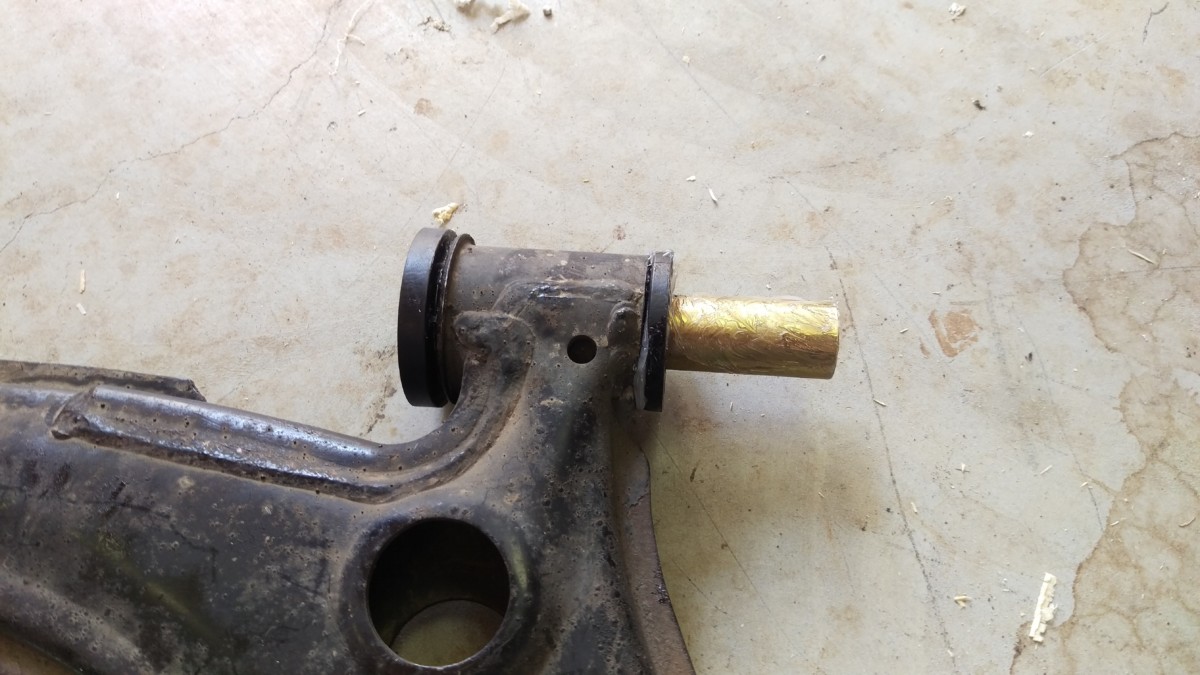
Cover the bushings and brass insert liberally with grease
A clamp or bench vise can force the bushings in
I like to use disposable nitrile gloves
For cleaning up the grease afterwards, I find brake clean
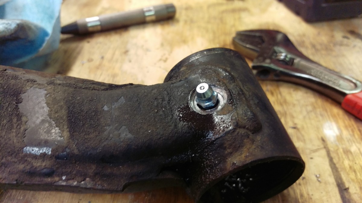
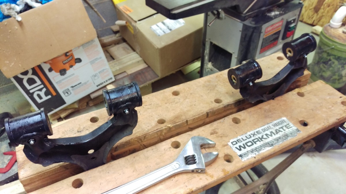
Installing the Grease Zerks
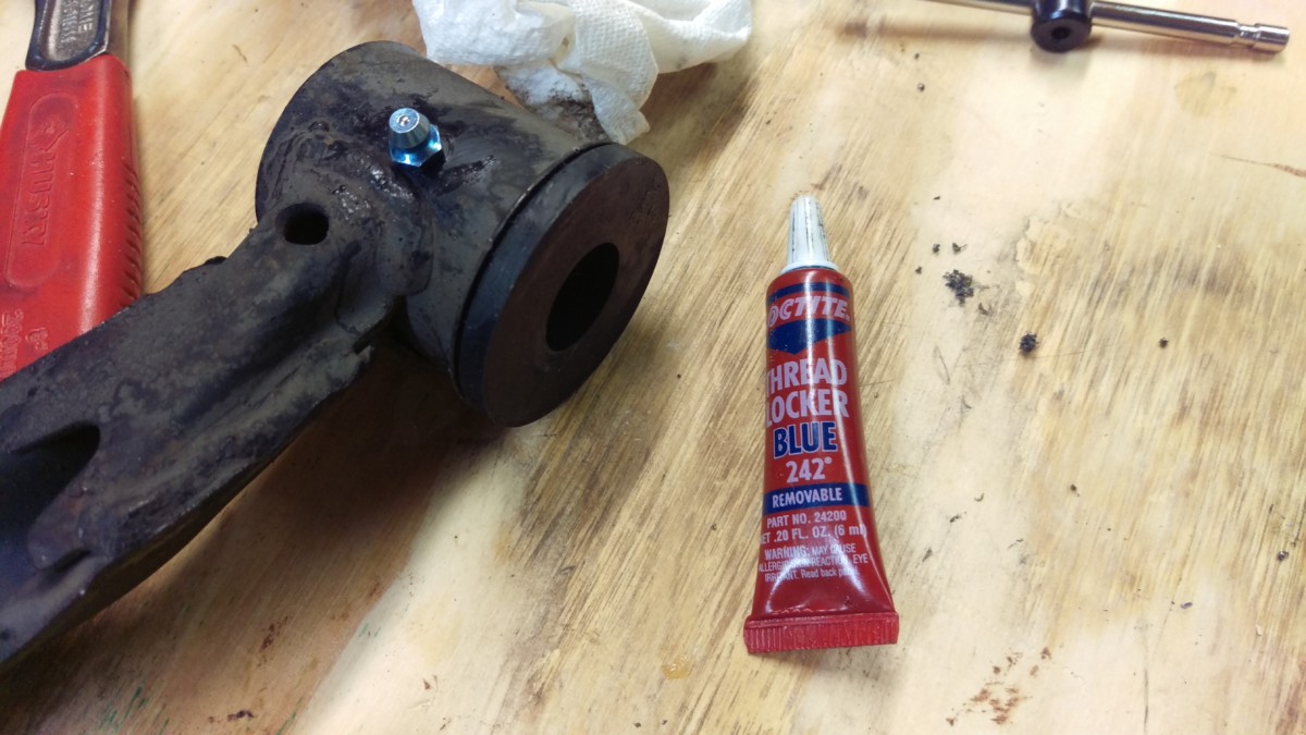
Zerk installed with some blue loctite
Final product again
Then you can go ahead and put the zerks in. I use some blue loctite to ensure they don’t come out, start them turning in by hand, and then snug them up with a wrench. No need to go full gorilla strength torquing them down. These control arms are ready to be reinstalled in the car.
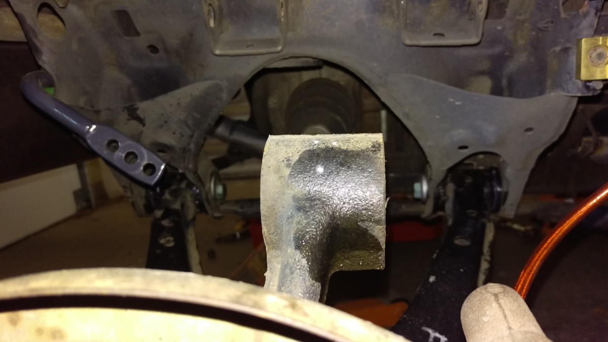
Reinstalling the Front Control Arms
The UCA Zerk locations in the car
The LCA Zerk locations in the car
Reinstallation is the reverse of removal. In general, put it back the way you found it. Also, don’t forget to return the LCA eccentric bolts to the positions you marked earlier. Follow the reinstallation guide in the coilover article to see how to properly torque everything down. You will need an alignment after doing this job.
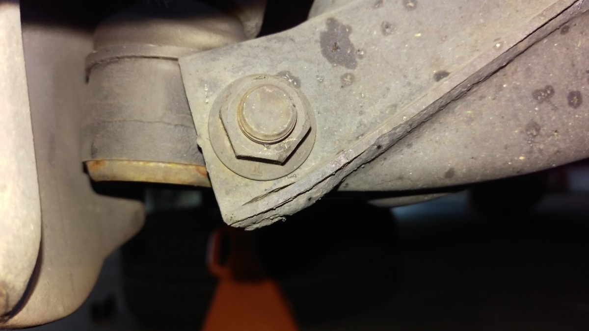
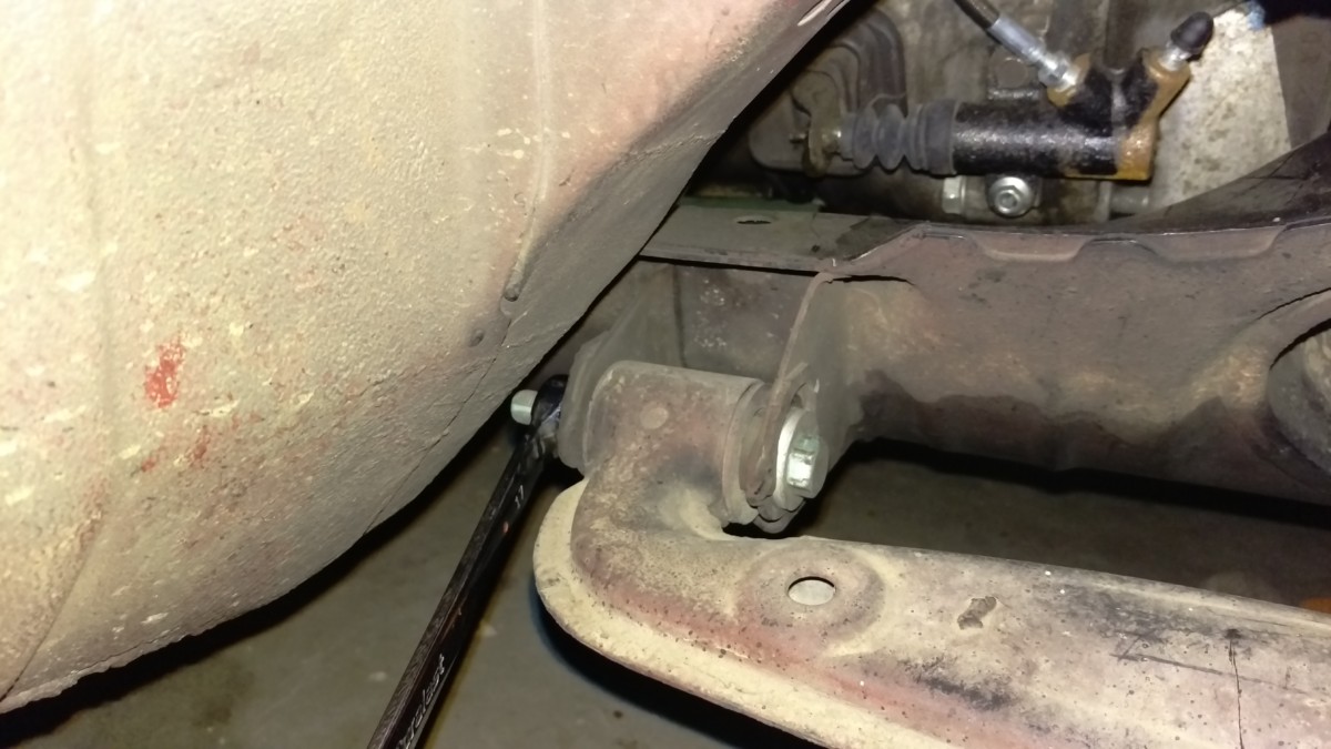
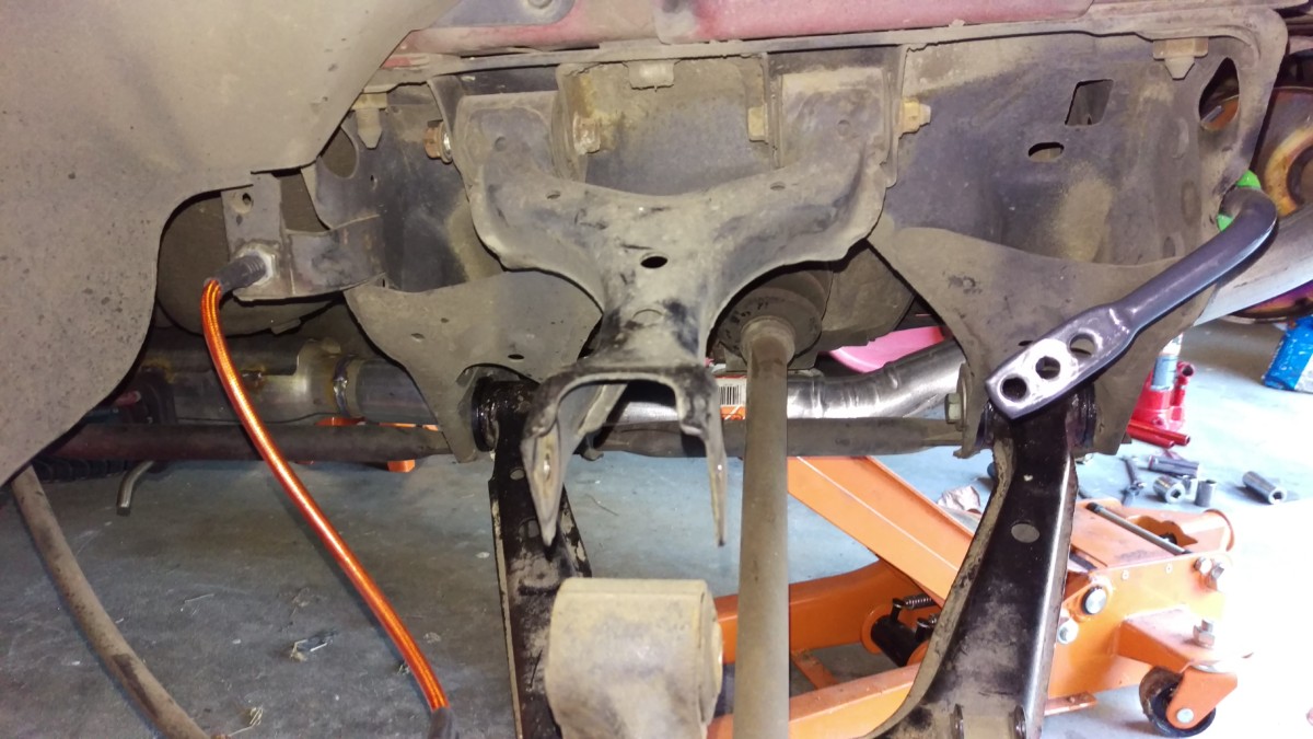
Removing the Rear Lower Control Arms
Outer LCA Bolts

Outer LCA Bolts 2
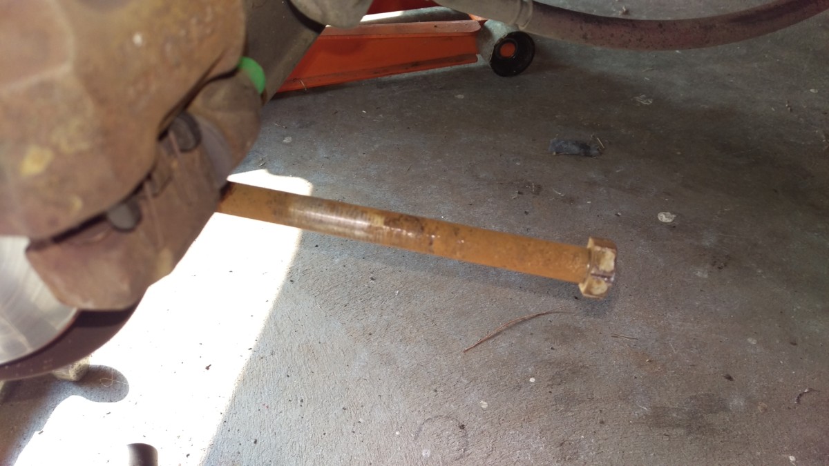
Once you have reinstalled the front suspension, lifted the rear of the car in the air, and removed the rear coilovers, you’re ready to proceed. The first thing I would do is work on the pictured outer lower LCA bolt. It can be a real bear to remove.
For me, the nut came off without a problem. The bolt, however, was rust welded stuck.
I primarily heated this area up with the torch
Freed
It eventually came free with a couple of things. I heated it fairly liberally with a propane torch, being careful not to burn anything rubber besides the a-arm bushings, which were getting replaced anyway. A hotter type of gas torch would have been even better. Then, I hit it with my trusty old Kobalt electric impact
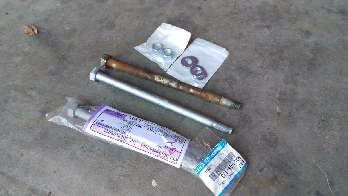
Replacement bolt
I ended up getting a replacement bolt for each side from Mazda. I had to get new nuts as well, but I didn’t realize they were M12x1.5 flange nuts, which are kind of hard to find around here. I used some M12x1.5 nuts and washers from the hardware store instead. The bolt is Mazda Part Number NA01-28-113.

The inner bolts are the same as the front
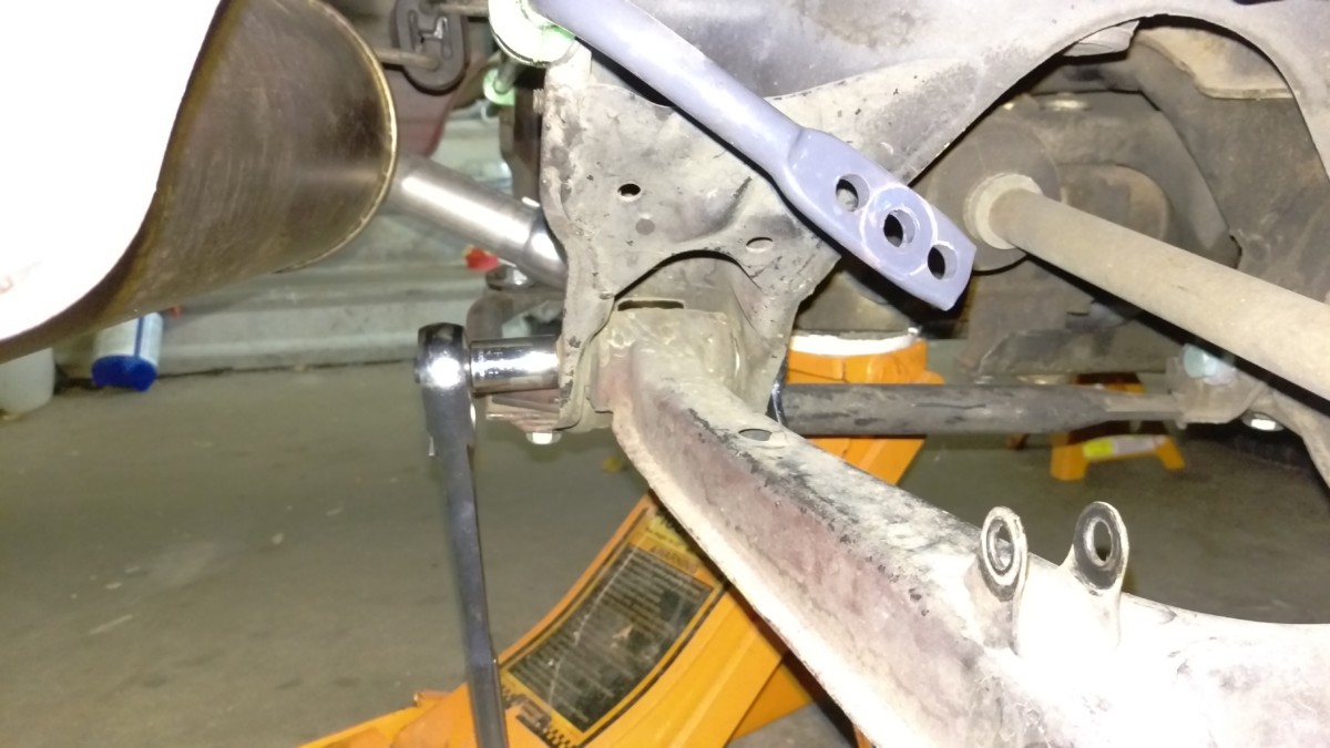
Mark the alignment and remove them
Fortunately, removing the long bolt was the hardest part for the rear. The inner long bolts come out exactly as they did on the front. First, mark the current alignment locations with a paint pen or sharpie. Then, pull both sets of nuts and bolts out. At this point, the a-arm should drop down.
Removing Bushings on the Rear Lower Control Arms
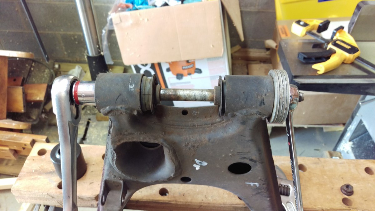
Removing the LCA Bushings
Removing the LCA Bushings
Removing the LCA Bushings
I ended up doing the lower control arms on both sides, followed by the uppers. I had thought this would make it easier, although in retrospect I’m not sure. In general, bushing removal is the same as for the front. The outer LCA bushings were close together, necessitating a bit of creativity.
Installing Grease Zerks in the Rear Lower Control Arms
The outer zerks are just like the front
The outer zerks are just like the front. They can go just about anywhere, although I ended up replacing these with some 90-degree angle zerks that were in my set. This gives easier access behind the wheel hub.

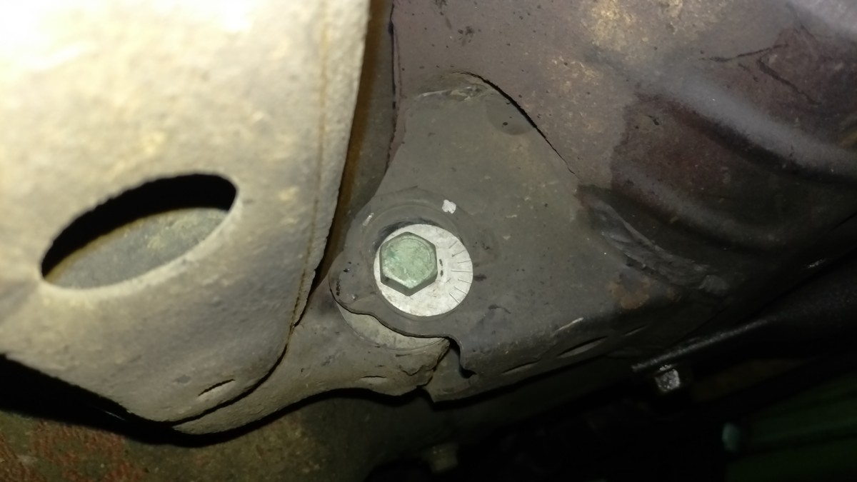
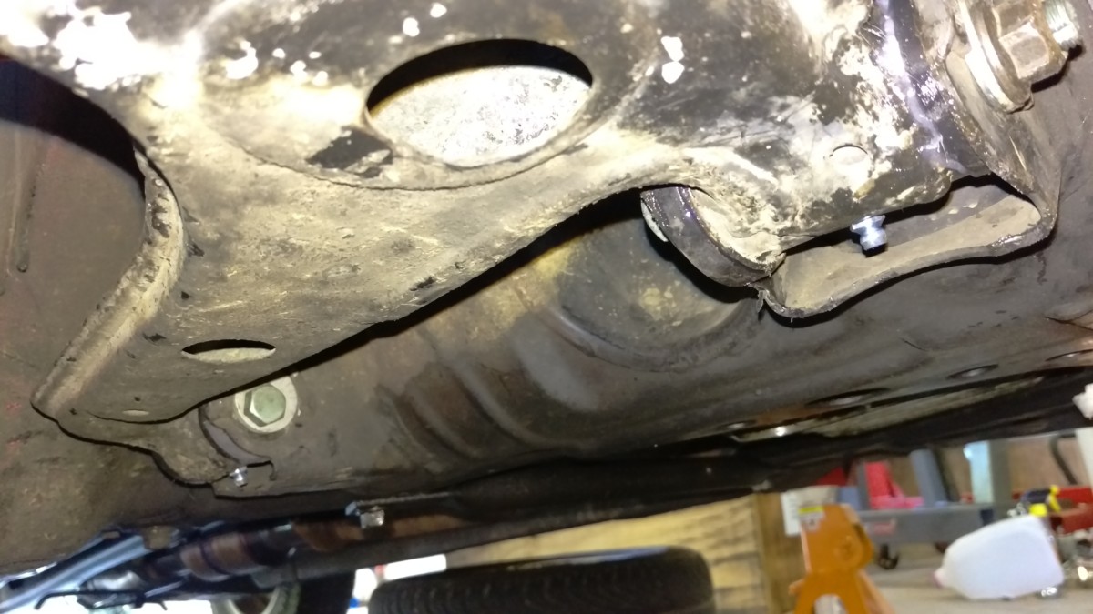
This hole is already there from the factory
I drilled out the inners
The inners work well if placed inside this hole that is already there from the factory. I drilled the hole for the tap first. Then, I went back and used a 1/2″ bit to remove a bit more material surrounding the hole. Finally, I hit it with a bit of Rustoleum black spray paint to help prevent rust. Otherwise, this part is just like the others.
Reinstalling the Rear Lower Control Arms
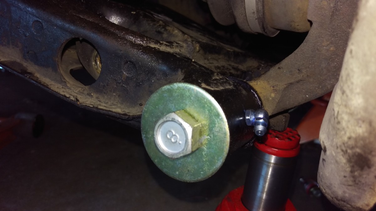
Left side outer, with angled zerk visible
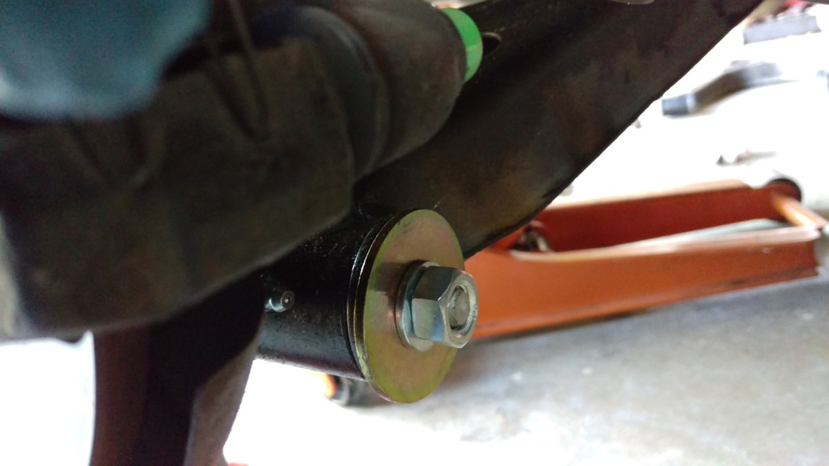
Right side of the same outer
As you can see, I ended up replacing the straight zerks with some 90 degree angle ones before installation. You can also see the fender washers that come with the bushing kit installed in this picture, as well as the new bolt and nut.
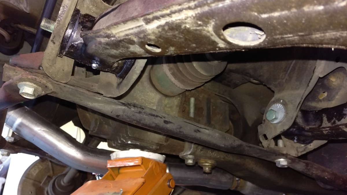
The inners after installation
The inners go back in just like the fronts. Don’t forget to realign the eccentric bolts. You will still need an alignment after this job. Placed inside of the factory hole like this, they easily clear the subframe at full droop.
Removing the Rear Upper Control Arms
Separating the UCA from the hub
Support the hub so the brake line isn’t stretched
The rear uppers are pretty easy, as there are only 3 short bolts to worry about. Have something handy to put under the wheel hub. Just like the front, you want to make sure there’s no strain on the brake line. Go ahead and undo the wheel hub from the UCA as pictured. Then, you can undo both of the bolts holding the UCA to the subframe.
Rear Upper Control Arm Grease Zerk Locations
The inners are identical to the LCAs
The UCAs finished
The UCA inner zerks are located identically to the LCA inners. I again simply drilled out the zerk hole, used a 1/2″ bit to drill out the material above it, tapped it, and hit it with spray paint. Then, I installed the new bushings just as before.
Rear Upper Inner Bushing Replacement

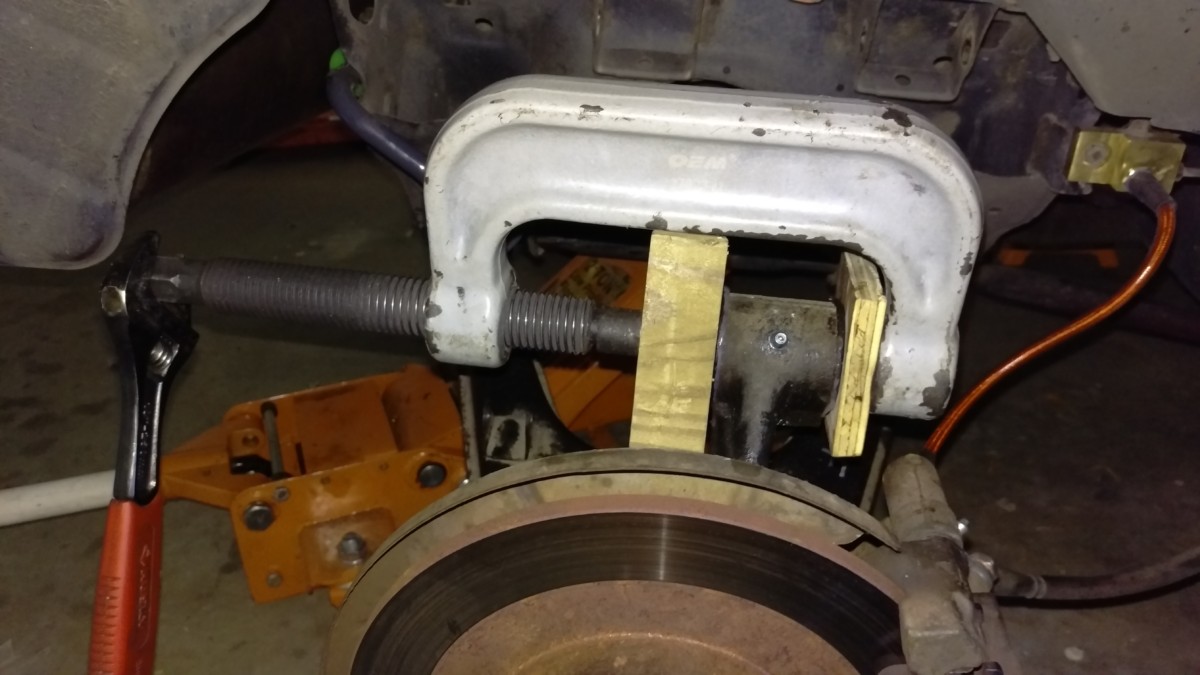
Press the bushing out as before, except in the car
The rear upper inner bushing is a little odd because it’s part of the wheel hub assembly. Therefore, it’s easiest to change it in the car. First, I removed the bushing with the ball joint separator clamp as before.
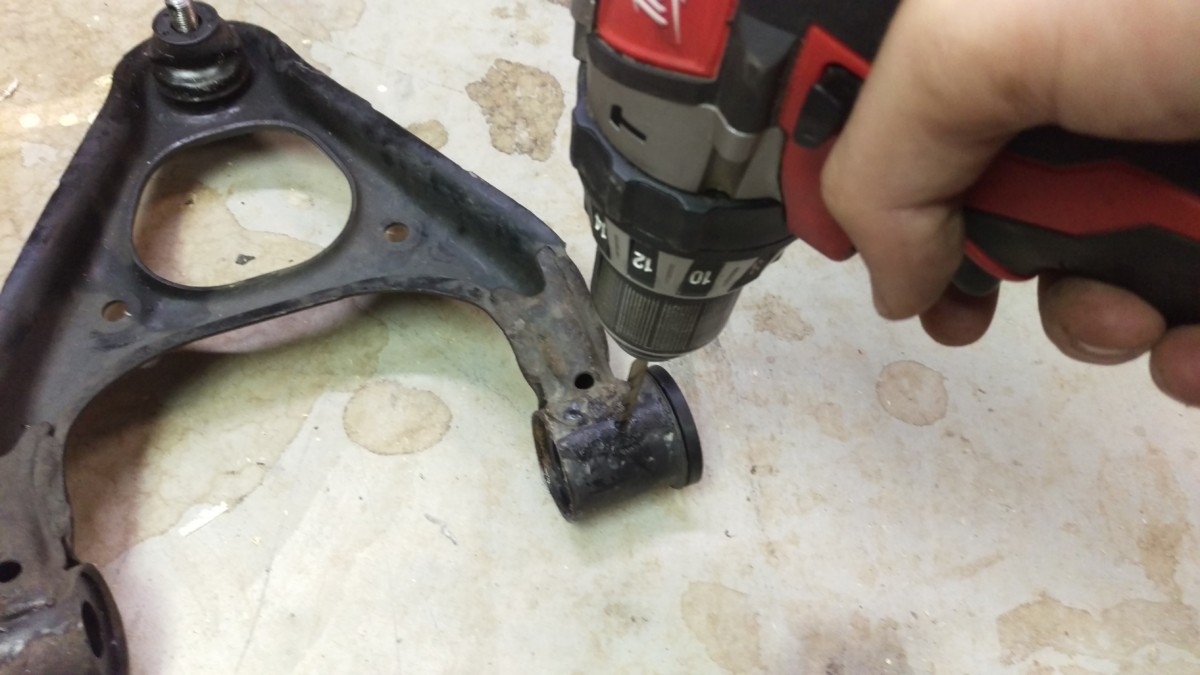
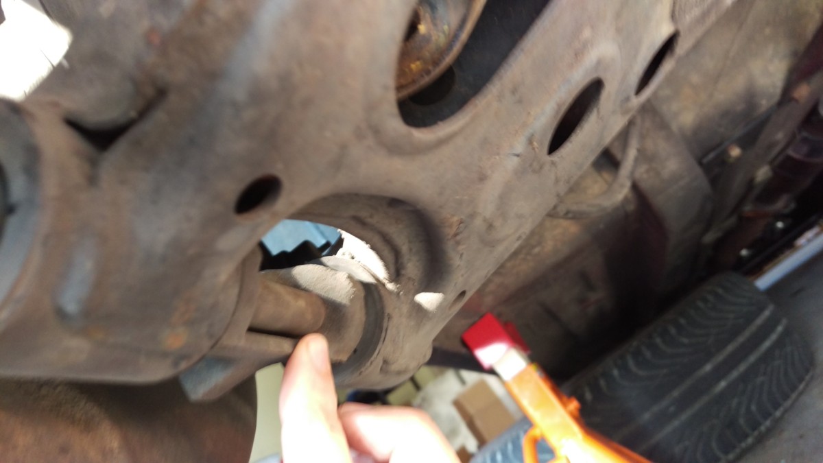
You have to drill the hole with a hand drill
Then you can mark and drill the hole with a hand drill. I placed it as shown because it made it easiest to drill it straight on. There’s also plenty of room to get a grease gun on it later. After that, I tapped the hole and added the zerk just like the others.
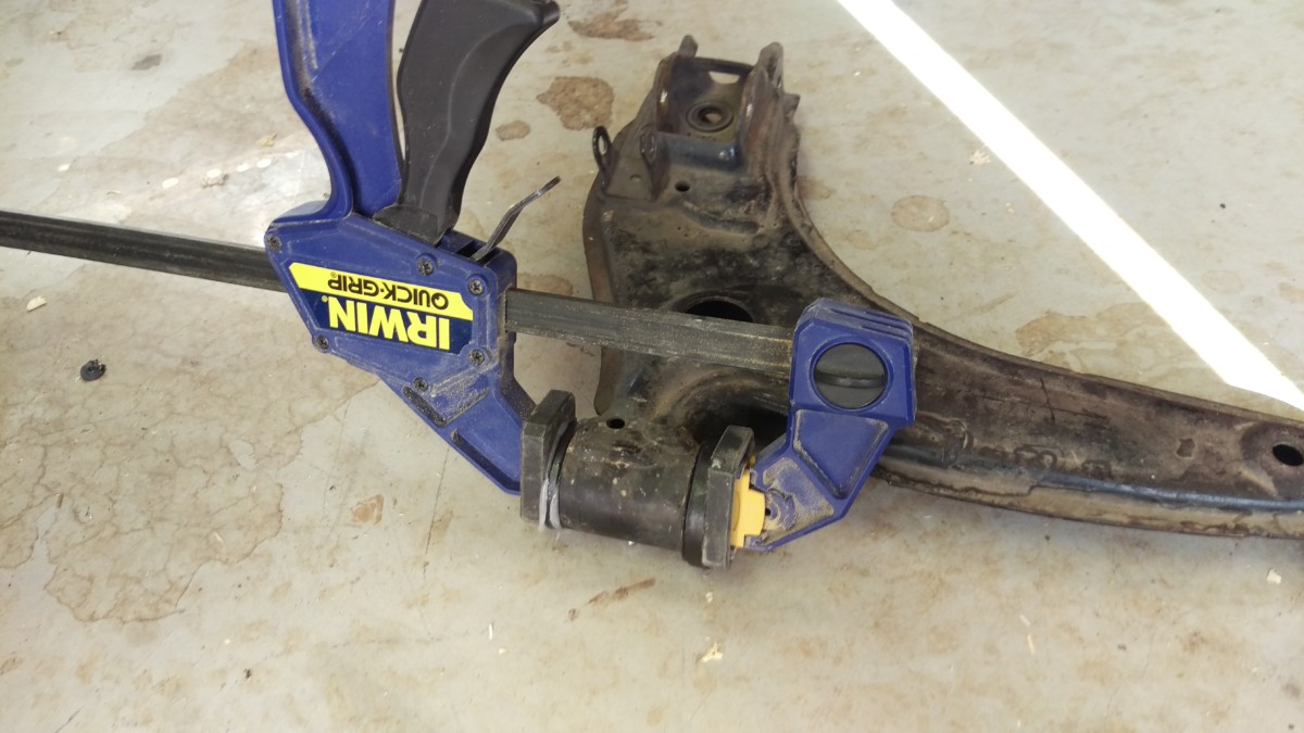
Pressing in new bushings with clamp and blocks of wood
Since I couldn’t use a bench vise and these bushings were a bit difficult, I ended up pressing them in with the ball joint clamp and a couple of blocks of wood. At this point, the upper control arms could go back in the car.
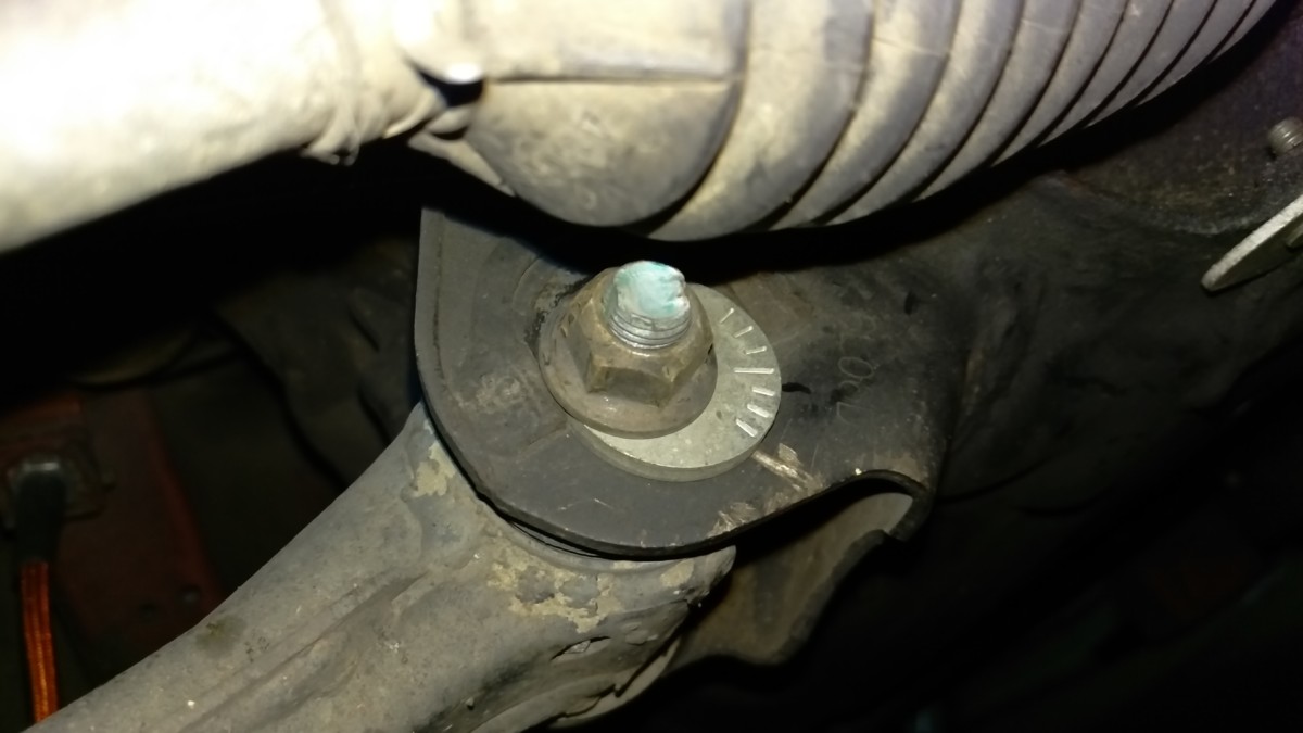
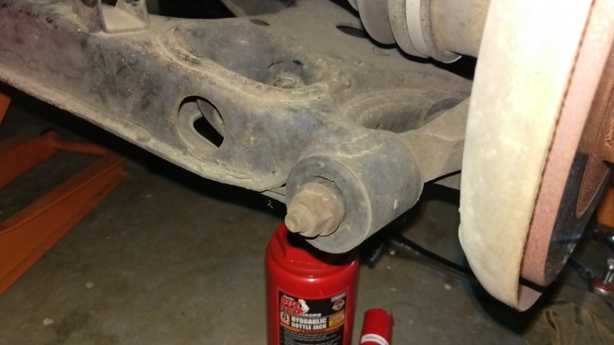
Rear Upper Control Arm Zerks in Car
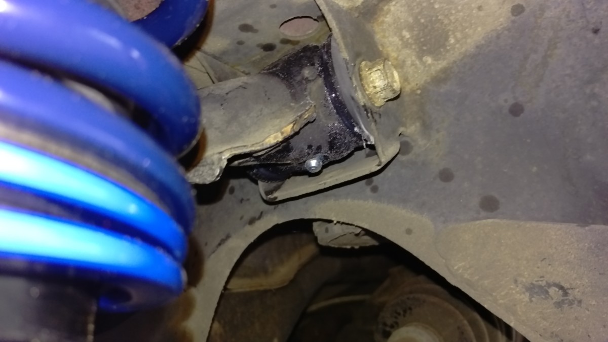
The UCA zerk after installation
Here is where the UCA zerks end up being located after everything is back together. At this point, you again want to reinstall everything just as you removed it. Don’t forget to realign the eccentric bolts and torque everything down with the suspension loaded as described in the coilover article.
Conclusion
This is really a fairly easy job to do yourself. Miata control arm bushing replacement can even be done without a press, making this job straightforward for the home mechanic. I found that the polyurethane bushings did increase ride stiffness noticeably, especially for the first few hundred miles. If you’re particularly sensitive to this, you may want to stick with rubber. If you track or autocross your car, you’ll probably appreciate the increased firmness and grip.
[…] take pictures of the actual ball joint replacement, but it’s fairly straightforward. I have a writeup describing how to disconnect the upper control arms from the spindle. Additionally, you should probably remove the coilovers first, so that you can pull the entire upper […]
Ahem. Lovely guide but please change “The ball joint should pop right out with little fuss.” to: “Might come out with a mighty bang and the control arm might hit your knee if it’s not stuck in a vice”. Happened to “a friend” of course 😉