Converting 12V Power to Turn Off in New Edge Mustang
Bluetooth FM transmitter for stock radio
When I wanted to start using Amazon Music Unlimited in my car, I grabbed one of these cheap Bluetooth FM transmitters
The bluetooth dongle linked simply plugs in to the car’s cigarette adapter power. Bluetooth audio from your phone goes through the device and is transmitted to any radio via a built-in FM transmitter. It works surprisingly well, and the device includes skip back/forward song buttons, which I end up using way more than I expected. with these buttons easily accessible near the shifter, I can find the music I want really hands free.
The Problem
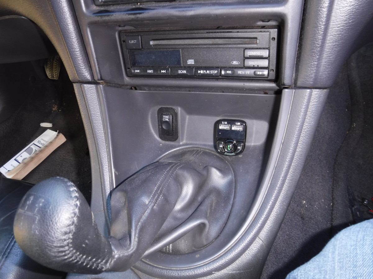
The big downside is that Ford has both power outlets in the mustang set to be always on, whether the car is on or not. For charging cables, etc, this is not a big deal or can even be convenient. However, for a Bluetooth device to be on 24/7, that means my phone will hook up to it if I’m simply too close to the car, even if I’m not actually driving. Very annoying!
The Solution
Relay
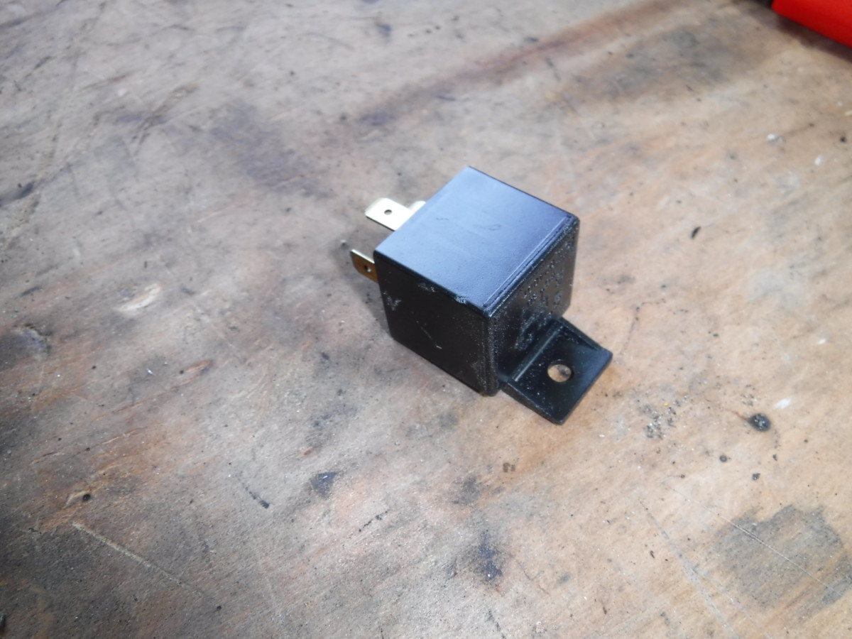
Fortunately, converting 12v power to turn off when the car turns off in a new edge Mustang is pretty easy. The trick is using a relay, which is basically an electric switch. I had the one pictured lying in a box of spare parts, but relays like this

The goal here will be to tap into another circuit on the car that turns on and off when the car does. Using a relay, this can be tied to the Mustang’s existing 12v power. These instructions are for a Mustang with traction control, as I use that as a source of switched 12V power. If you don’t have traction control, you’ll have to find another source of 12V power, such as the ignition wire to the radio.
Explanation of Relay
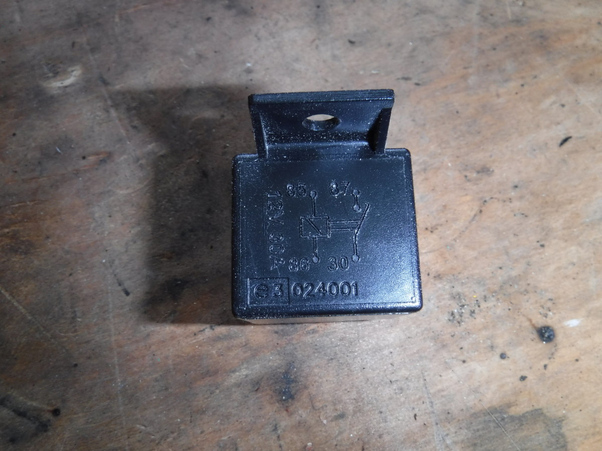
Relay should have a diagram on the top
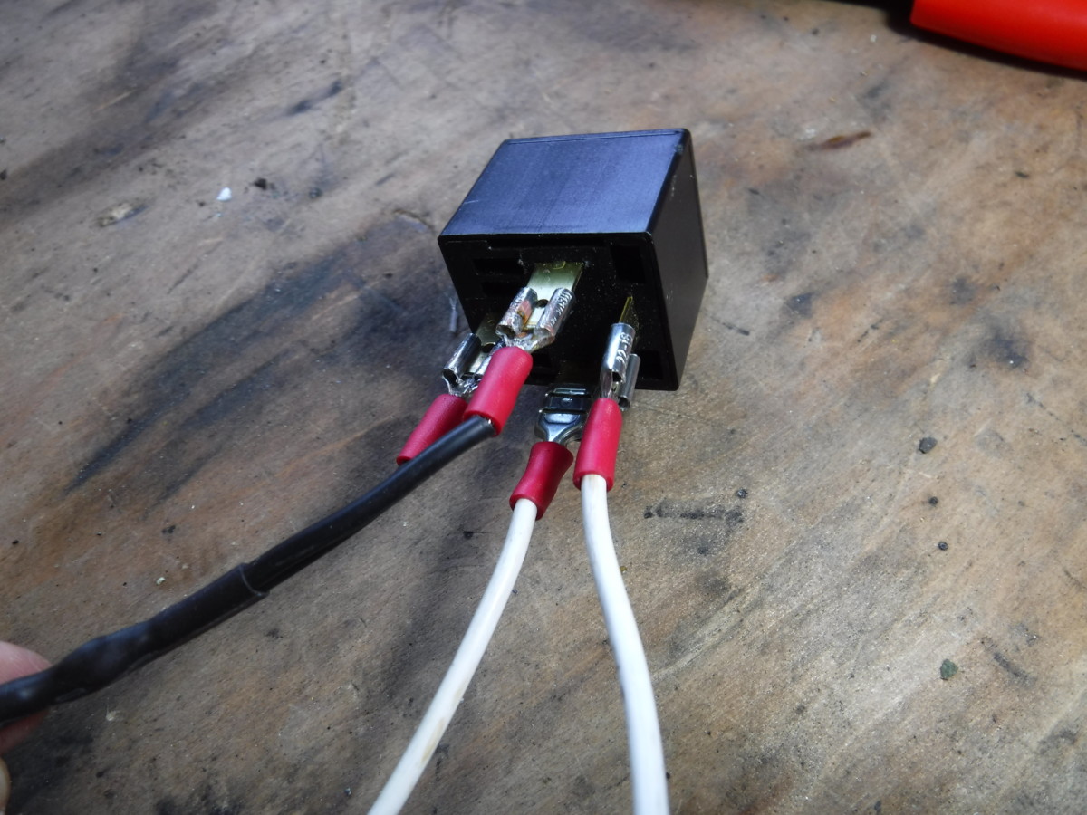
Begin by setting up the wiring to the relay. This is much easier before it goes into the car. The diagram on top of the relay explains how to wire it. As I said earlier, the relay is basically an electrical switch. When power is sent through two pins, the other two will be connected together. In this case, the diagram says that if power is applied across pins 85 and 86, it will connect pin 87 to pin 30. This is a quite common configuration for an automotive relay, including the numbers.
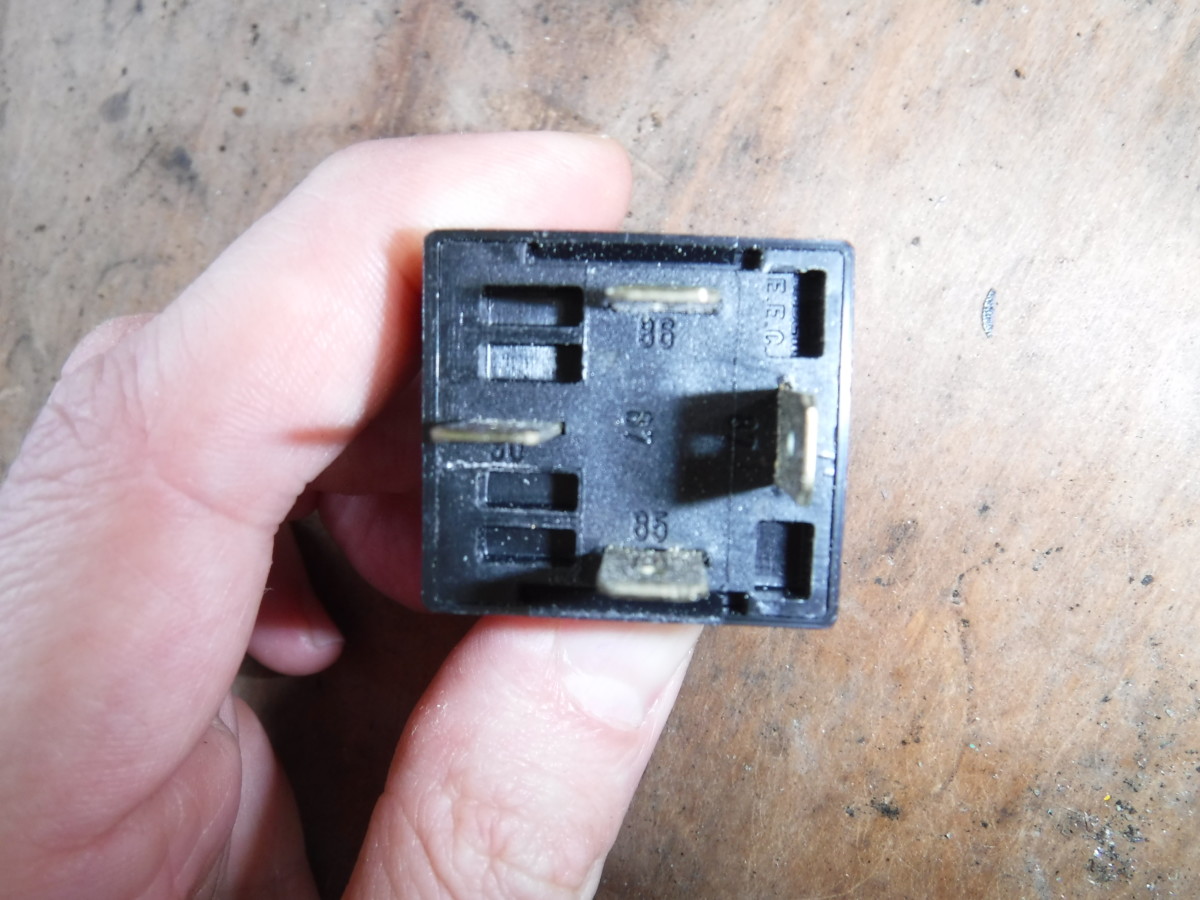
Labels on bottom of relay
If you examine the underside of the relay, you can see that it is labeled with numbers corresponding to the diagram on top. Connect pins 86 and 30 to a common ground. Then, hook pin 85 to any 12V source that turns on and off with the ignition. Hook pin 87 to the cigarette lighter ground wire.
The important thing here is that ground from the cigarette lighter goes “through” pins 87 and 30, while the switched 12V source goes “through” pins 85 and 86. When 85-86 “sees” power, it will connect 87 to 30, completing the 12V cigarette circuit.
Preparing the Wires
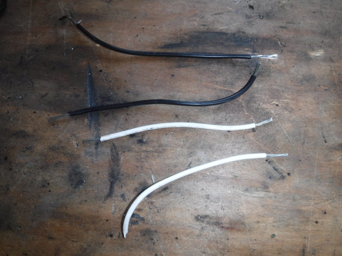
You don’t need much
I used some 16 gauge wire I had laying around for this. Pick a wire size based on amperage. Vehicle 12V power adapters are typically 10 amps. In this case, 16 gauge wire is rated for 10 amps up to 50 feet, so this should be plenty for such a short run. If you use too small of a wire gauge to carry too much current, the wire will burn up.
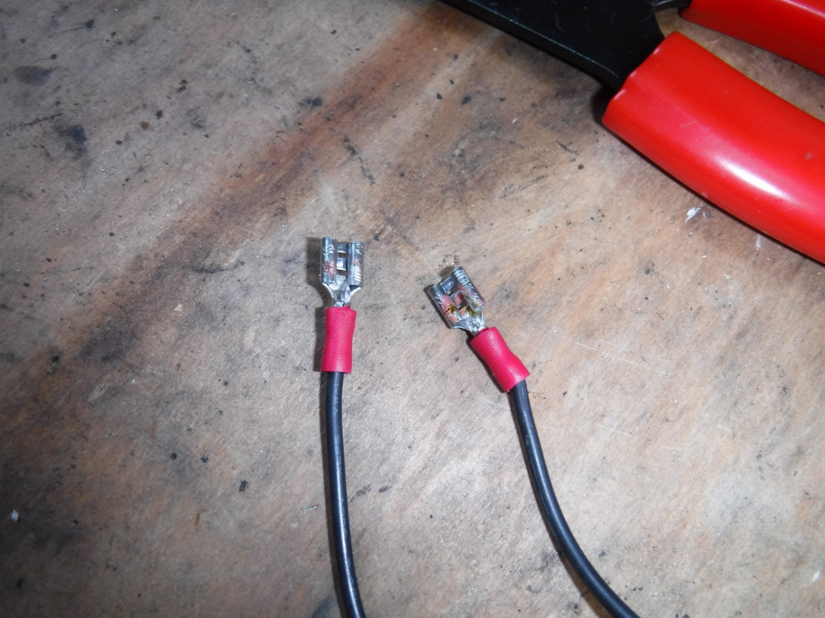
I like to solder as well, to ensure it doesn’t slip out
For these crimp on connectors, I prefer to crimp and then add a bit of solder to ensure the wires don’t slip out. Some people like to crimp automotive connections, insisting that vibration will cause soldered connections to break. For relatively small gauge wire like this, I think that’s nonsense and have had more trouble with crimped connections slipping out than soldered connections work hardening. Supposedly a “proper crimping tool” works better, but I’ve yet to see one. Your mileage may vary.
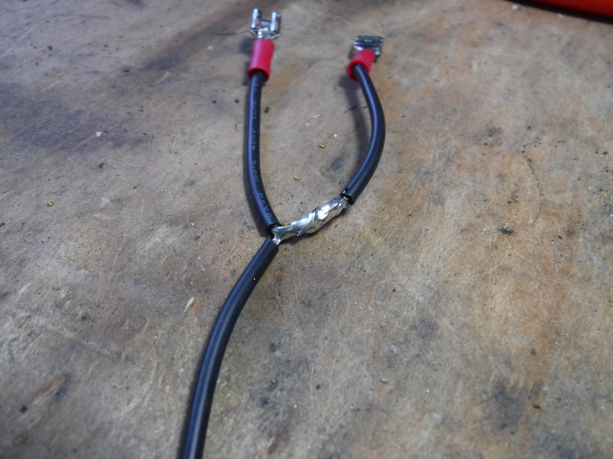
Crimped and soldered up this wiring
Applied some heat shrink to tidy things up
I set up the ground wires in this y-shape just to tidy things up. Having two separate ground would be fine as well, but involve more wires.
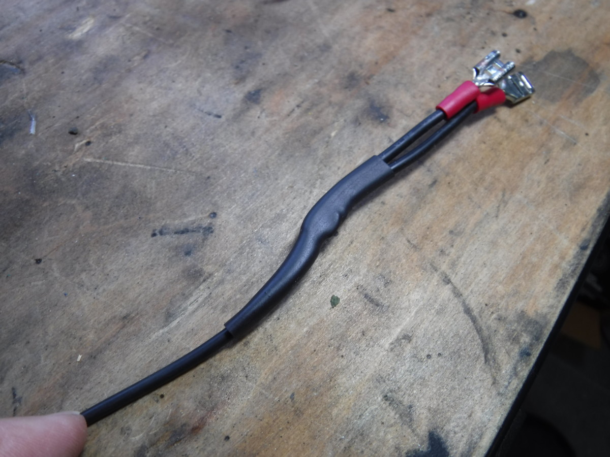
Definitely use heat shrink on any soldered connections. Heat shrink provides great insulation as well as some mechanical rigidity around the soldered joint, plus it looks nice.
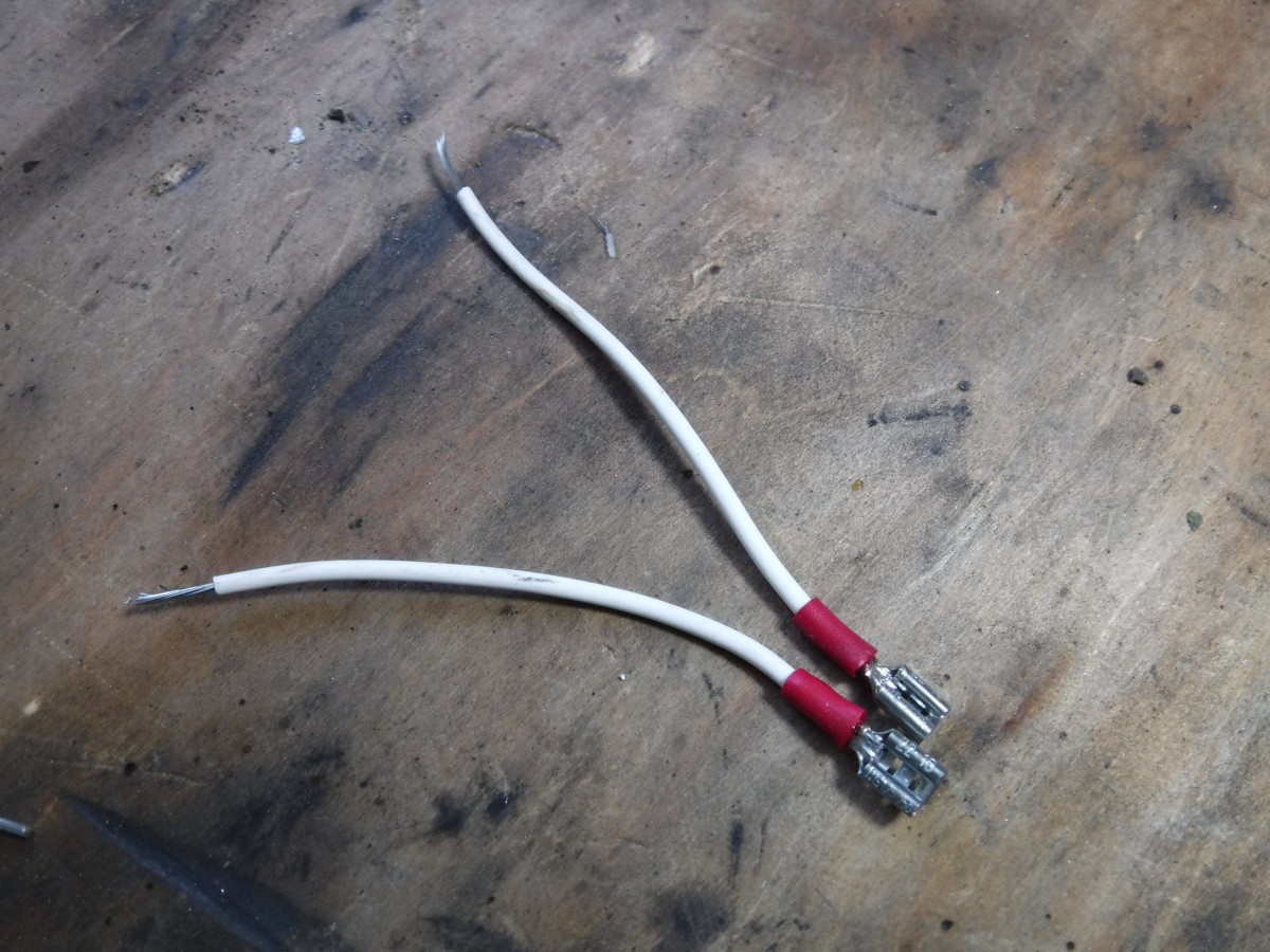
The other two wires get the same treatment
The other two wires get the same treatment, except that they’re not connected to each other.
Final prep of the Relay
Relay
Tape
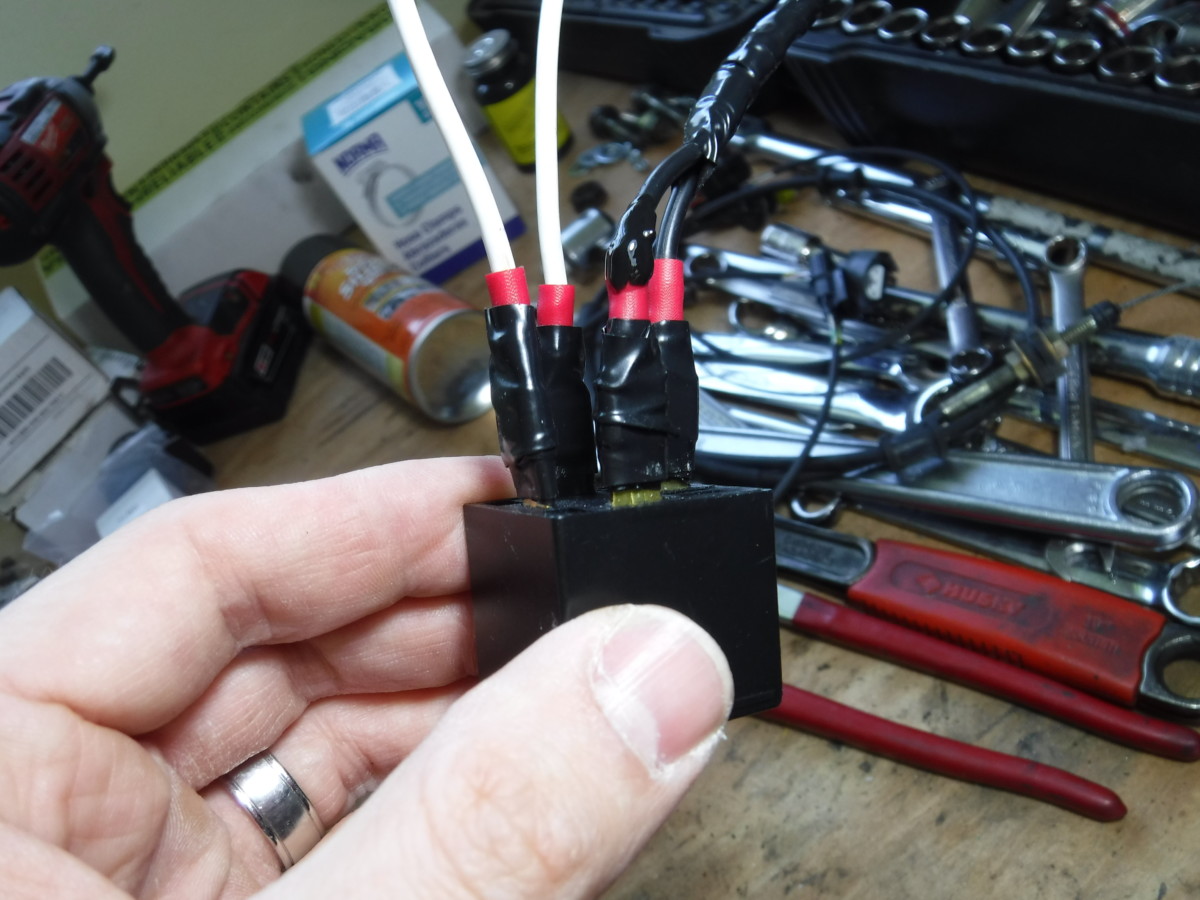
At this point, connect the wires to the relay as described earlier. I also taped them up with electrical tape to secure and insulate them. Heat shrink probably would have been better, but I guess I got lazy.
Ready to go to the car
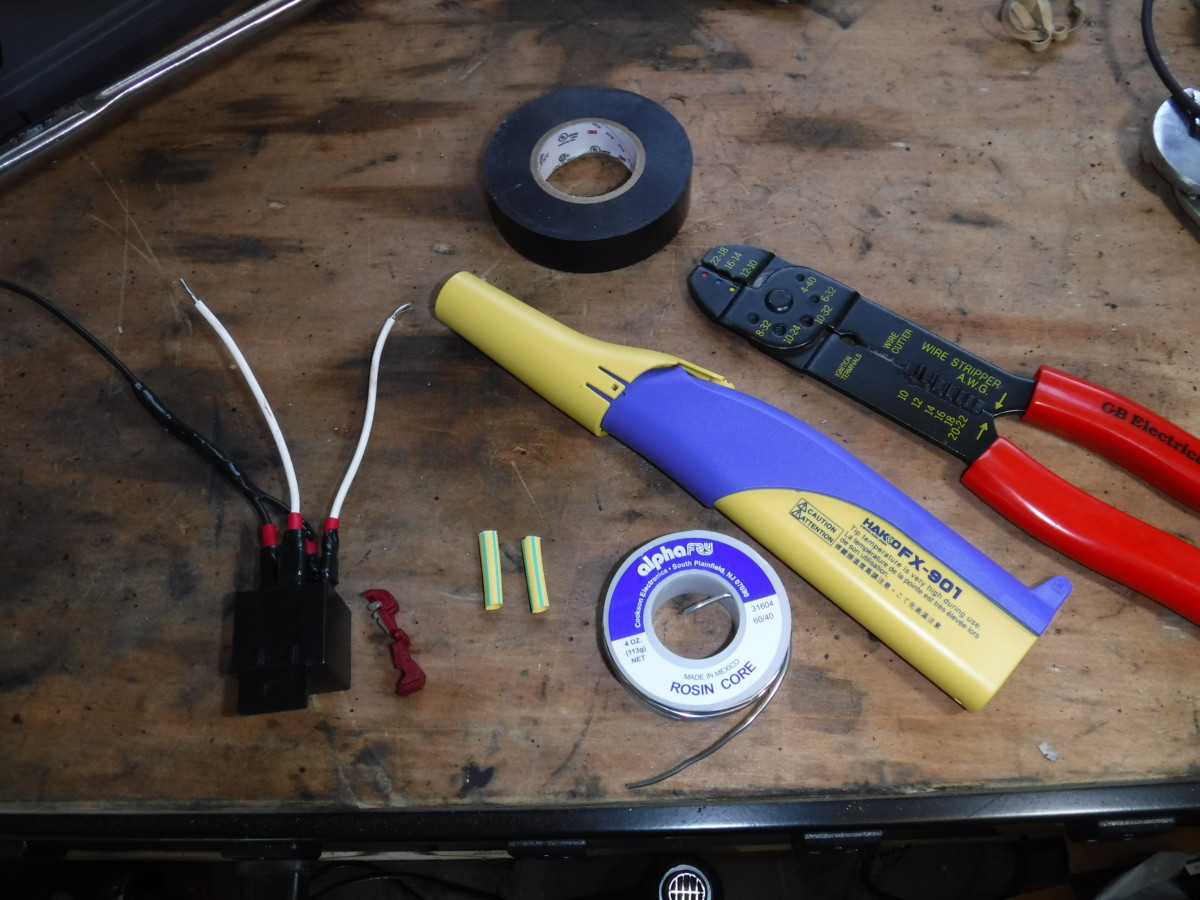
Here are all the required items to bring to the car. Besides the prepped relay, I have a portable soldering iron, wire stripper


Regarding soldering irons, I have the Hakko FX-901

For a less portable station, I highly recommend my Hakko FX-888D
Unplugging the 12V Power Fuse
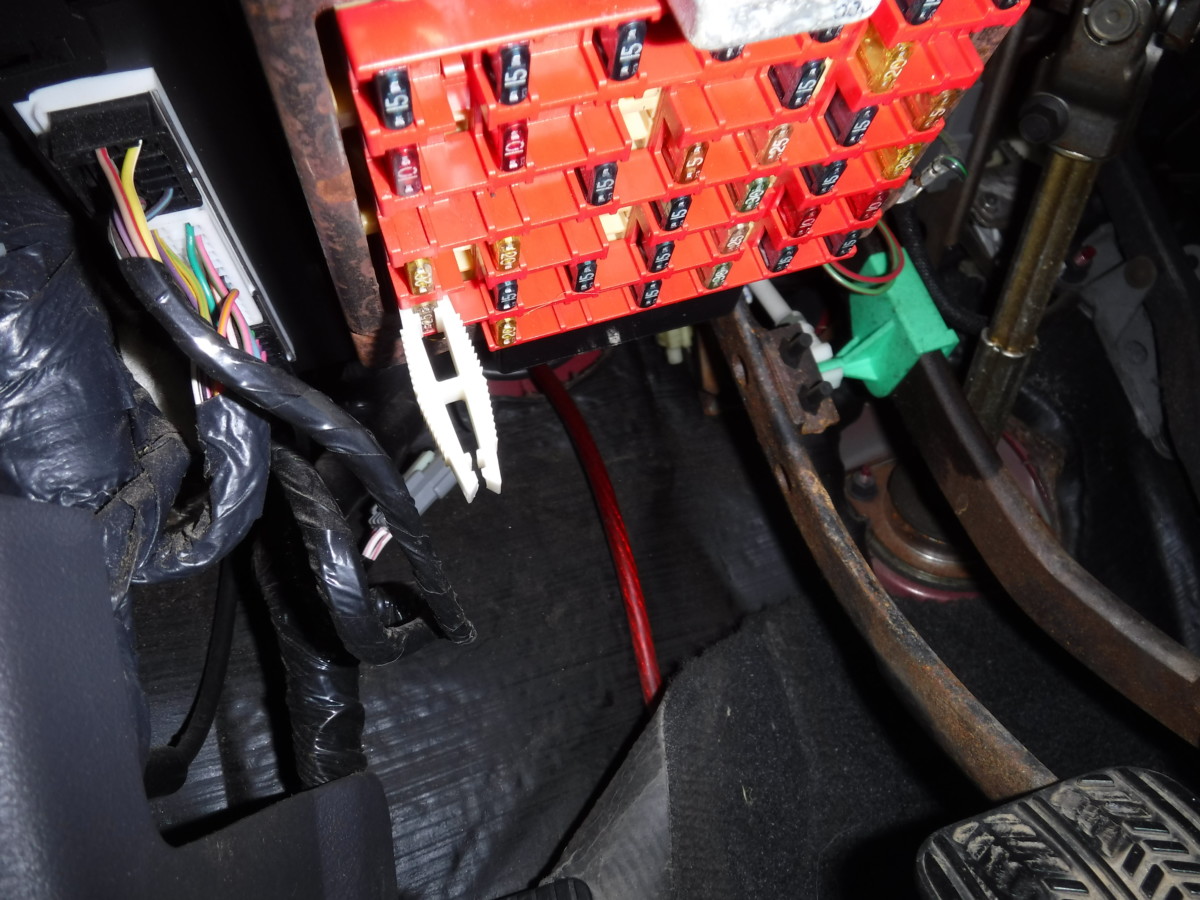
Pulling the fuse
Pull the fuse to the 12V outlet before proceeding to cut up the wiring, as this will cut power to it. You could alternatively simply unplug the car’s battery. Either way, you don’t want to work on the wiring with power running through it, or you could short it and blow a fuse.
Getting to the Plug
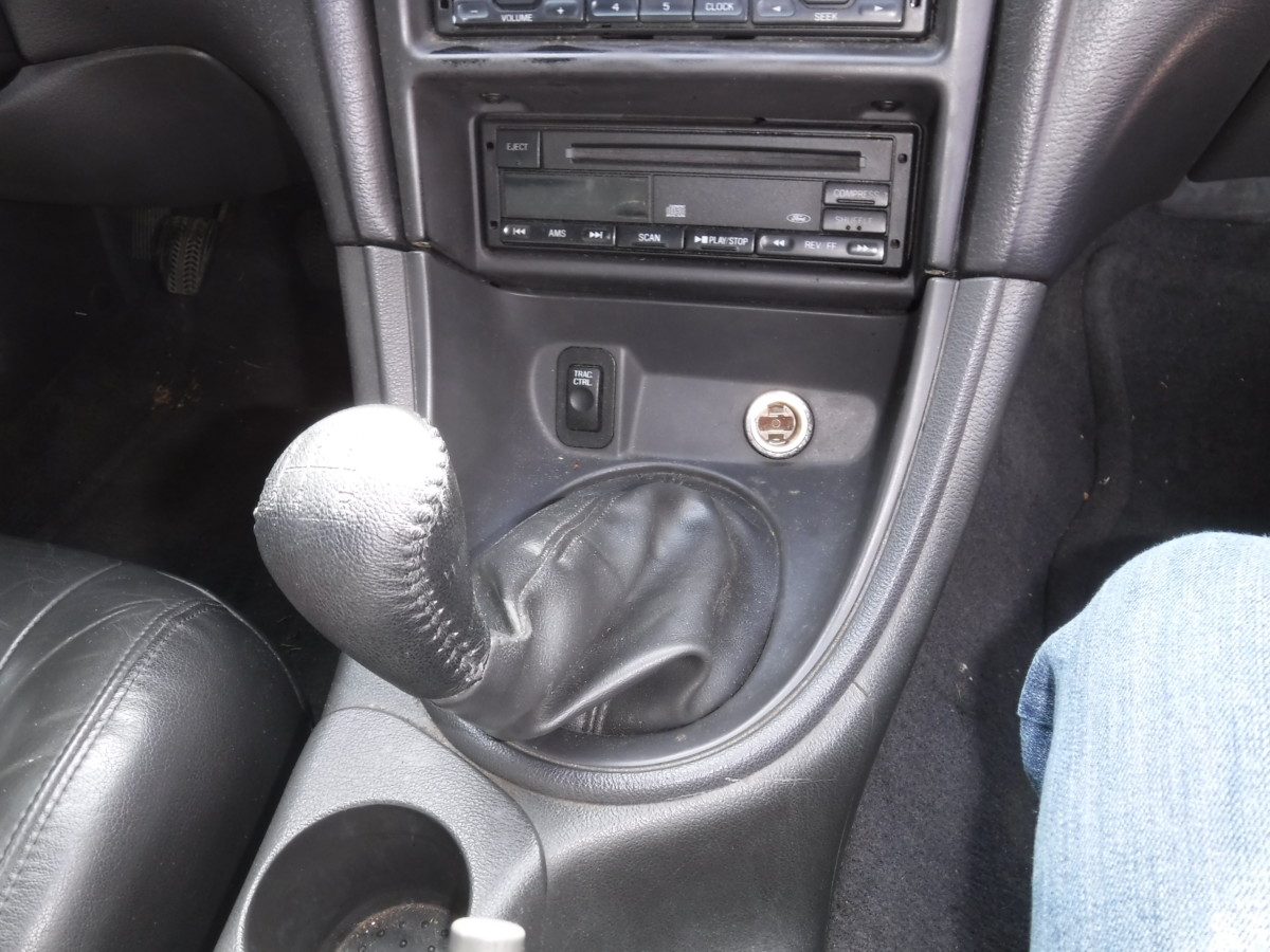
This trim piece simply pulls straight out

It’s now loose
I chose to make this front power source switched. To do this, first pull the trim piece out. It’s held in with tabs and simply unhooks by pulling straight back.
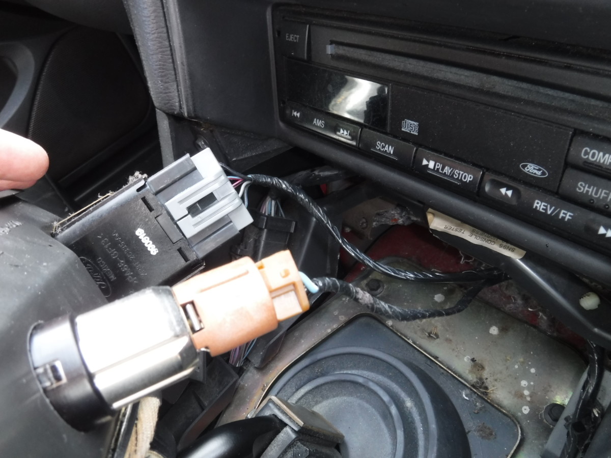
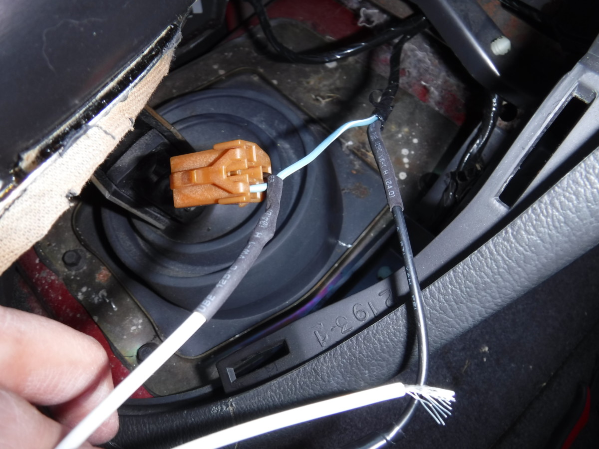
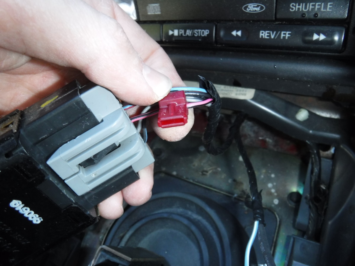
Traction control and power plugs
On the back of the trim panel, you’ll see the traction control plug, if you have it, as well as the 12V power plug. If you don’t have traction control, you’ll have to find another source of switched 12V power, as mentioned earlier, such as the radio.
Splicing the Wiring
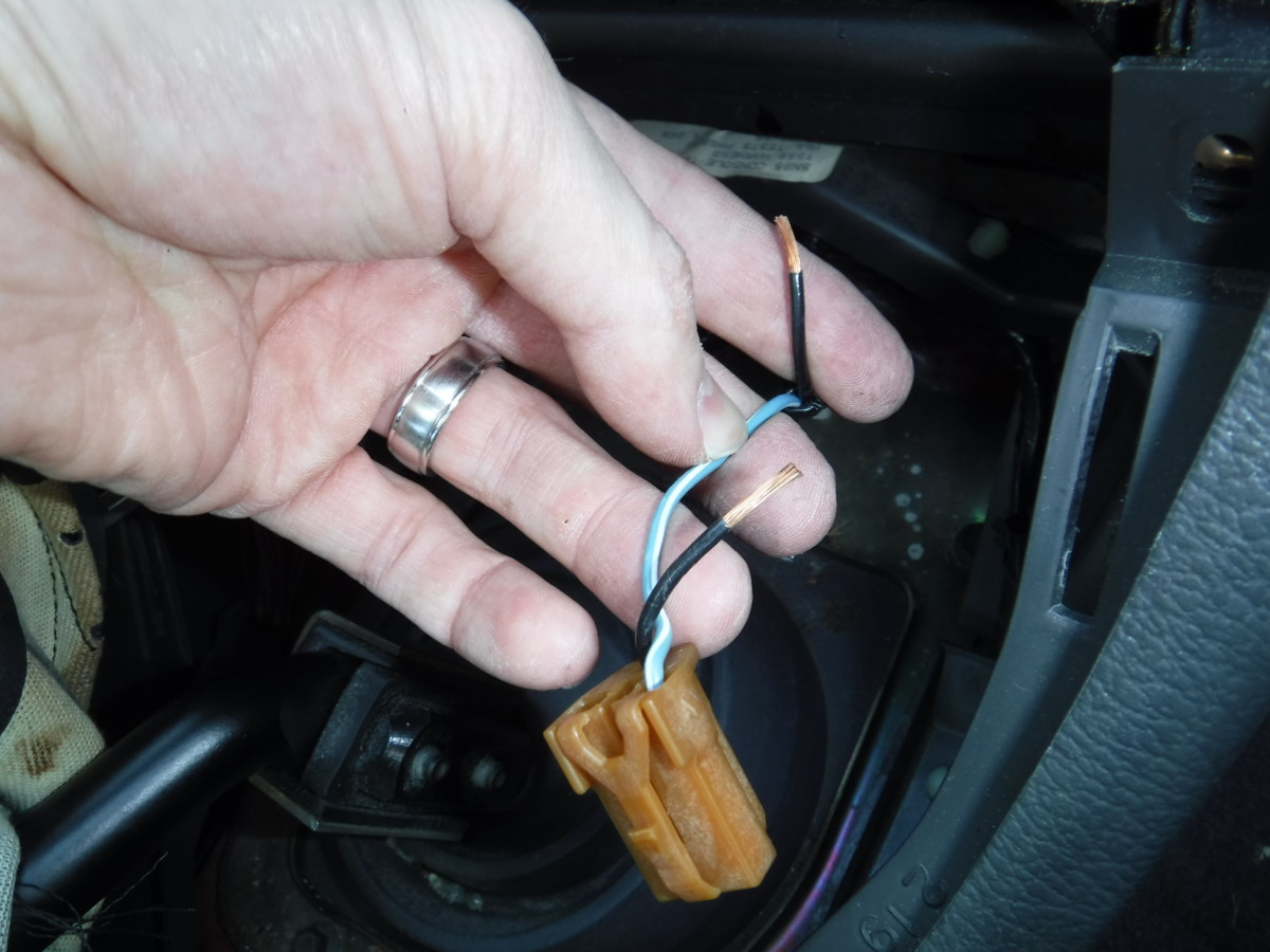
Cut the ground wire from the power plug and strip both ends back
Cut the ground wire from the 12V outlet and strip both ends back as shown. The relay will connect/disconnect the ground connection, which will turn the outlet on and off.
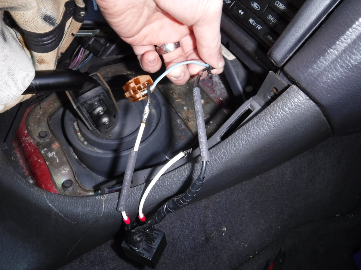
Three wires done
Zoomed in view
When you clip the plug ground wire, it will be in two halves. Let’s call them the plug half and the car half. The plug half goes to the white wire on the relay connected to pin 87. The car half goes to the combined black ground wires on the relay. I connected these with solder and heatshrink, although you could use a crimp-on connector if you prefer.
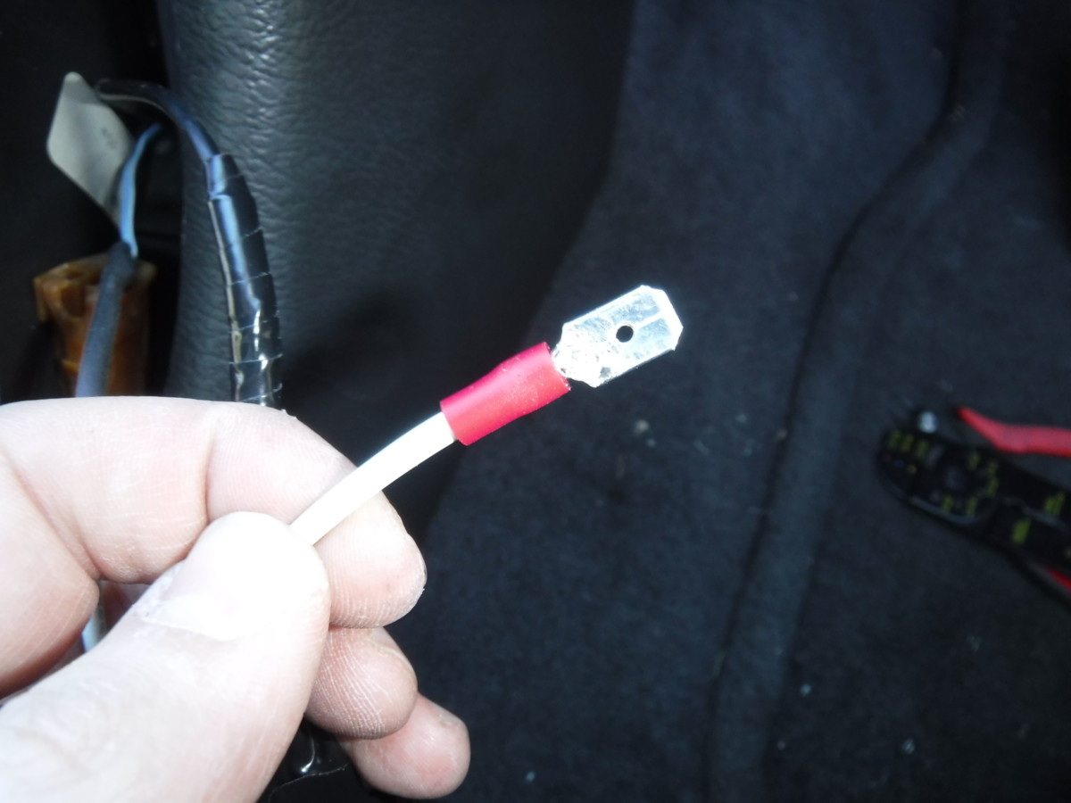
Final wire gets a spade connector
The final white wire gets a spade connector, as it will be used with the vampire tap
Clamping the tap around the signal wire
Clamped and ready
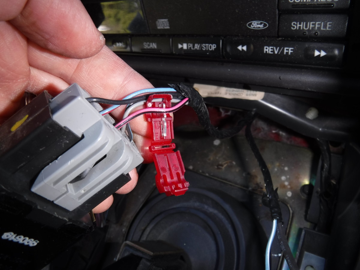
The traction control has switched 12V power on this pink and black wire. You may have to peel back some tape to expose it. These vampire taps simply snap in around the wire.
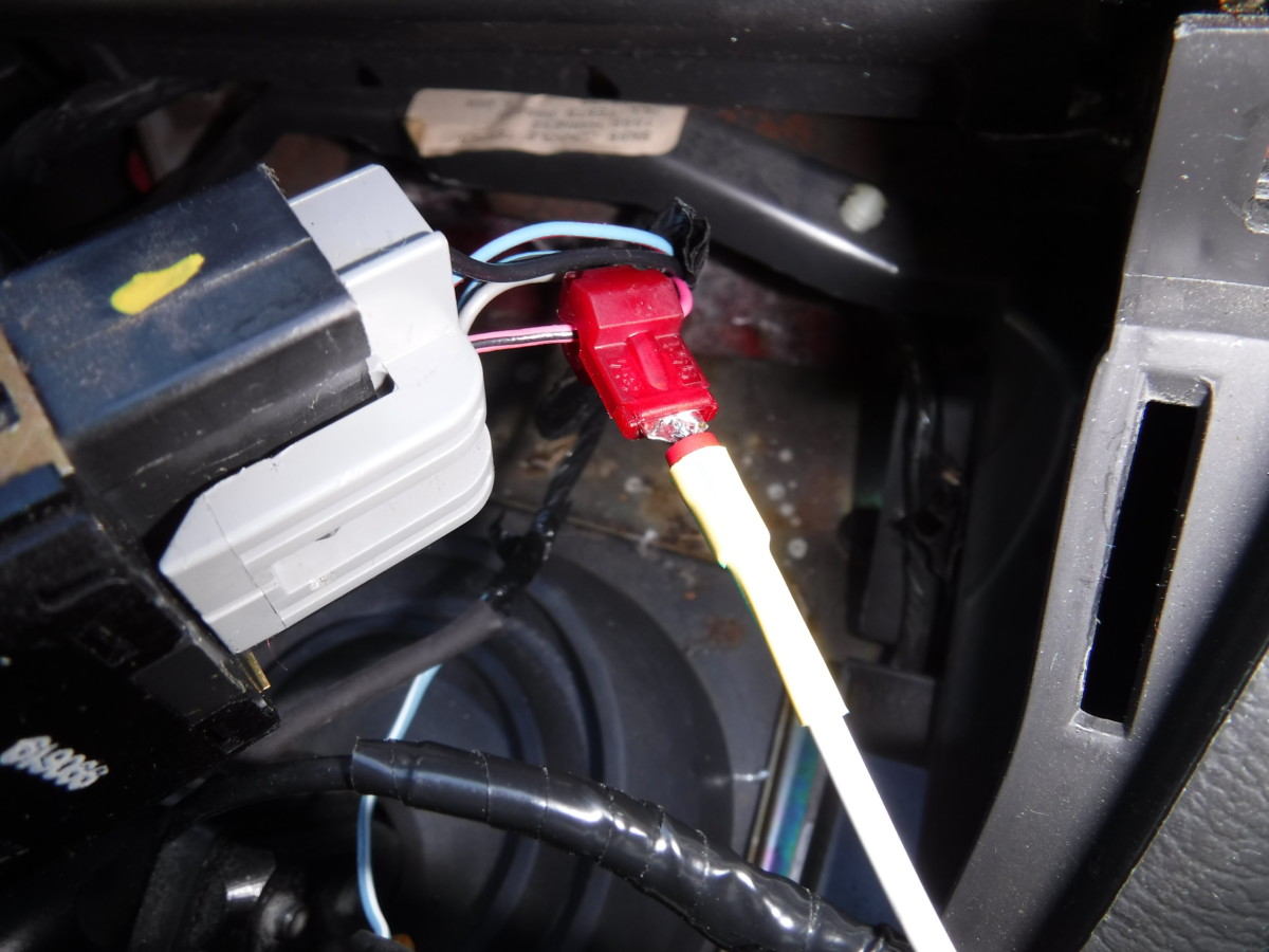
Spade connector plugs in to tap
The white wire with the spade connector, connected to pin 85 on the relay, plugs right into the end of the vampire tap. I generally put heat shrink around this connection to help hold it in place, although it should be a snug fit regardless.
Put it Back Together
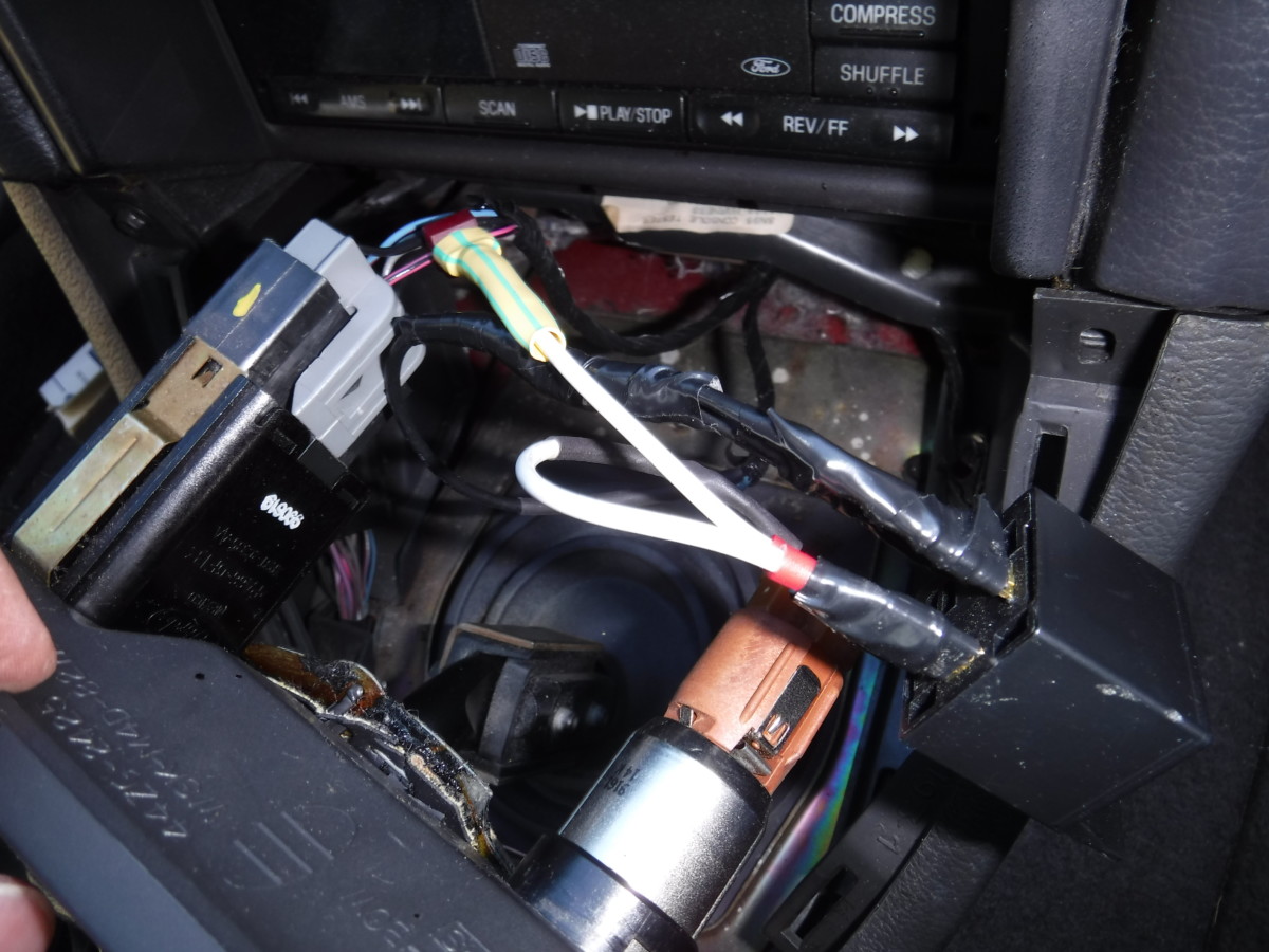
Wiring all finished
Here is a shot of the completed wiring after heat shrink and tape. At this point, you can reinstall the fuse or plug the battery back in and test it out.
Bluetooth FM transmitter for stock radio
My bluetooth adapter now turns on automatically when I start the car. The 12V power outlet near the center console is still constant 12V if I want to charge a phone or something while the power is off. This setup has proven to be quite convenient. I even like the location of the buttons on the bluetooth adapter, it’s pretty easy to lean over and hit the skip song button without distracting me from driving too much.