sub-$50 DIY 10hz Bluetooth GPS Receiver
Full Disclosure: I got this project from Aidan over at miataturbo.net. The original thread is here. There is also a thingiverse page on this, which includes all links plus a 3D drawing to 3D print an enclosure for it.
If you do HPDEs, autocrosses, etc, you will likely eventually find yourself wanting to get good lap timing. It used to be that you had to buy a standalone system to do this, which cost thousands of dollars. These days, you can get away with an app for your phone. There are several popular ones, including Harry’s Lap Timer and RaceChrono, available for both iPhone and Android. These apps will show you not only your lap times, but also more detailed information, so you can determine which lines are fastest and help improve your driving.
By default, these apps use a phone’s built-in GPS to get your location and speed. The issue with this is that most phones have a 1hz GPS unit. This means that they can get updated coordinates once per second. While this sounds good, it’s actually too slow for good resolution. Instead, it’s better to get one of the many available 10hz or better GPS units and connect them to your phone via bluetooth.
Unfortunately, the cheapest existing receivers are in the $80+ range, and they aren’t very reliable. However, dozens of companies these days make small GPS, bluetooth, and other modules that can be easily hooked together. This project involves 3 such components (Bluetooth, GPS, and USB), costing a total of about $20, and soldering them together.
Source: http://www.thingiverse.com/thing:698168
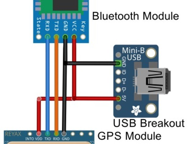
The diagram, taken from the thingiverse page, illustrates what will happen. You buy the 3 modules: bluetooth, GPS, and USB. Ground and power from the Bluetooth and GPS modules are connected to ground and 5V power on the USB module. Then, TXD (transmit) on the Bluetooth module is connected to RXD (receive) on the GPS module, and vice-versa. At the end of the day, your phone connects to the bluetooth module, and it forwards data to and from the GPS module. Easy peasy.
I’ll note here that this module does need to plugged in, there is no battery. Adding a battery, particularly the charging circuit, would add complication. Honestly, I find it easier to hardwire this once and forget it.
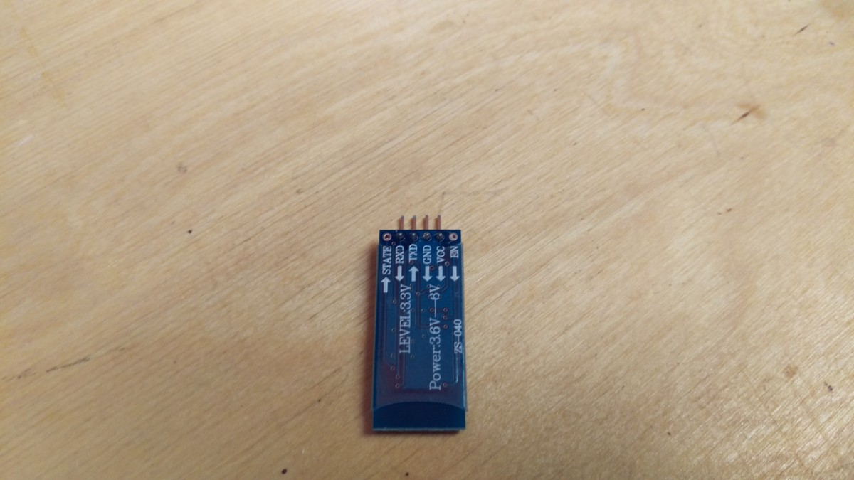
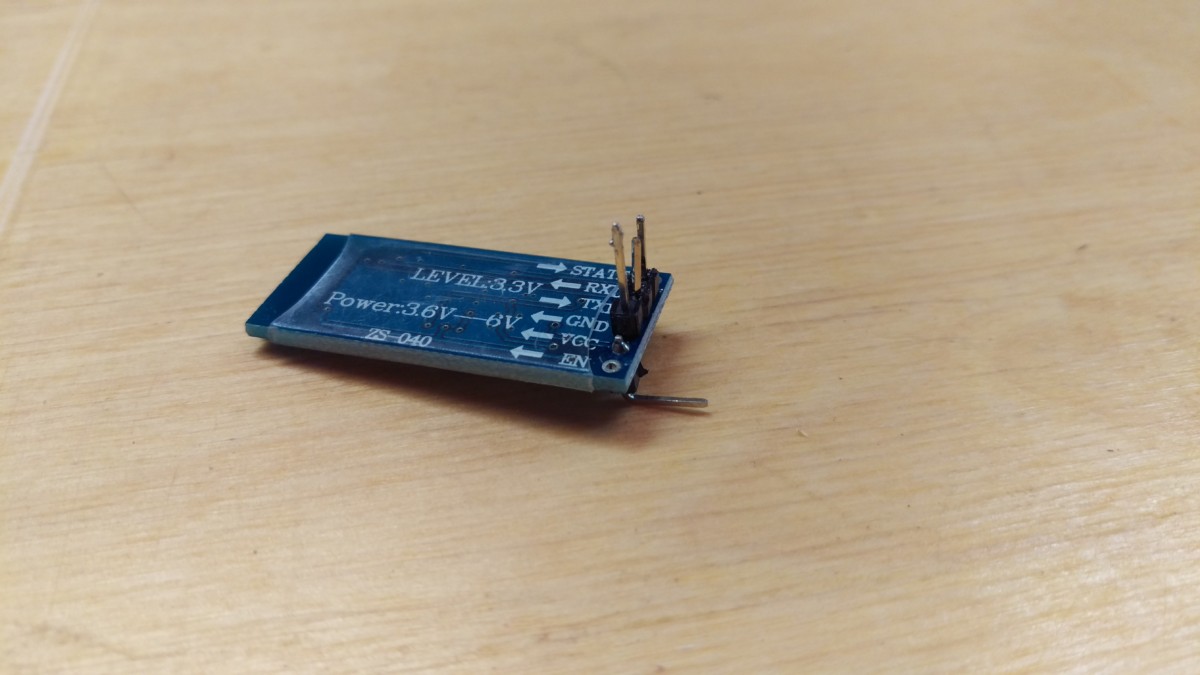
(Note: I’ve seen discussion on this project centering around using 5V power to the HC-06, stating it requires 3.3V. This isn’t quite true – the module itself does require 3.3, but the commonly purchased submodule, such as the I bought, includes a voltage rectifier allowing it to take between 3.3 and 6V, as it says on the underside. Further reading here.)
Shopping List
(Note: The price of these parts fluctuates _all_ the time. You can shop around Amazon, Ebay, Adafruit, Digikey, Mouser, etc and try to find the lowest prices – don’t forget shipping! A lot of these components ship from China, as well, so be prepared for slow ship times.)
Parts:
- HC-05
or HC-06
Bluetooth Submodule (Either one will work, I found the HC-06 a little bit cheaper)
- Reyax RY8253F GPS Module The older RYN725AI also works but is discontinued, as a commenter below pointed out. You want a GPS module that can do 10hz, has serial, has flash, and is powered by 3.3V to 6V with 3.3V logic.
- USB Mini Breakout Board
(Although I wish I’d gotten a USB Micro Breakout Board
, since I have more of those cables – should also work)
- Some double-length header pins
- Replaced by Reyax RY8253F above:
RYN725AI GPS Module (I accidentally bought the RYN25AI, which is a bit cheaper but has no flash or EEPROM to permanently store the 10hz setting. Some versions of the RYN25AI do have EEPROM – make sure you get one of these. If you make this mistake, you’ll simply have to reprogram the chip for 10hz when you use it, as the battery only lasts about a day. You cannot add EEPROM on afterwards.)
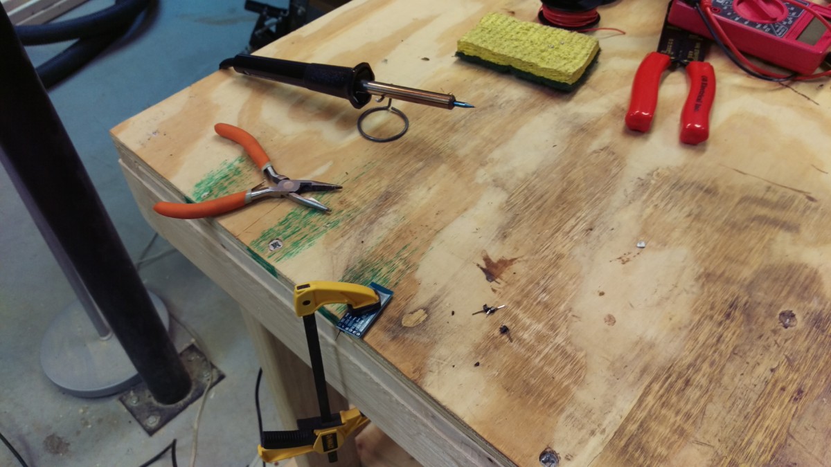
You also need a few tools, if you don’t already have them:
- A soldering iron
– A station like that is preferable, but I made do with a $4 Harbor Freight iron
- Quality fine solder
- This thing
to hold the boards is very helpful – I put some rubber tubing over the alligator clips to not damage the PCBs
- A bit of wire
- Pliers
- Wire strippers
help
- Solder wick
helps a lot if you screw up soldering – I wish I had had some


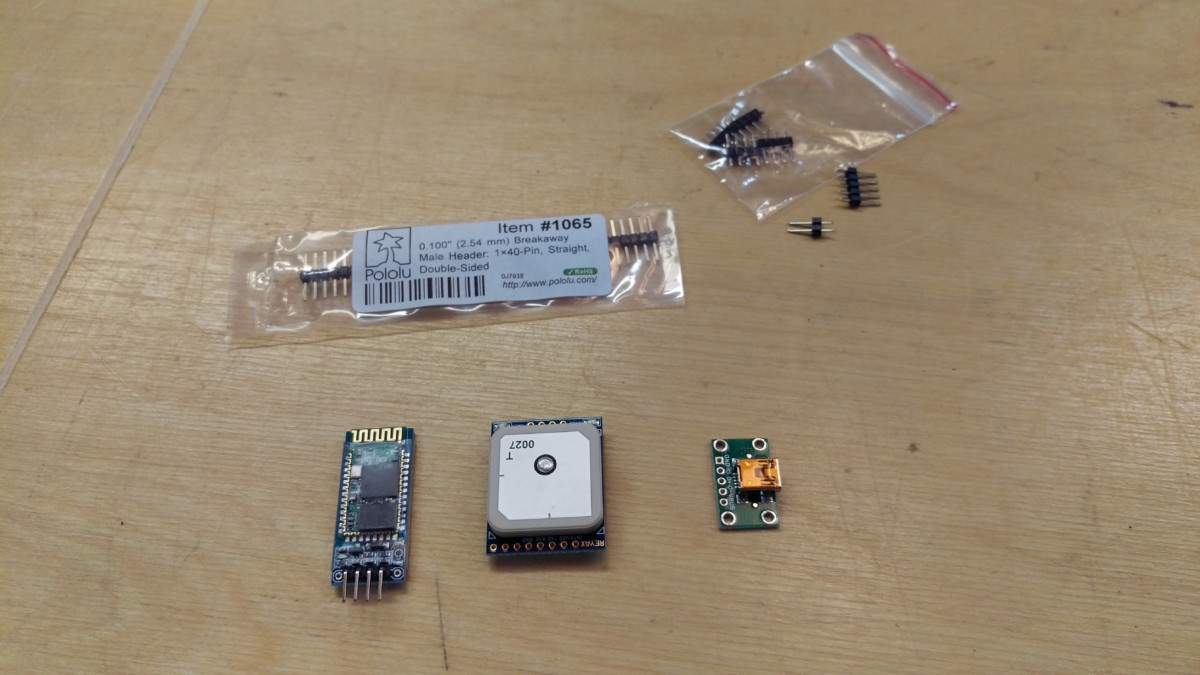
All of the parts required
Here’s a picture showing all of these parts ready to go.
Fixing the Bluetooth module
The HC-06 comes with pins pre-installed
The HC-06 will come with 4 pins preinstalled in VCC, RXD, TXD, and GND. This is fine for VCC, but we want to put some pins directly from the other 3 into the GPS module. We also want the chips (and the antennas) on each module to face away from each other. As such, you’ll have to remove three of these original pins.
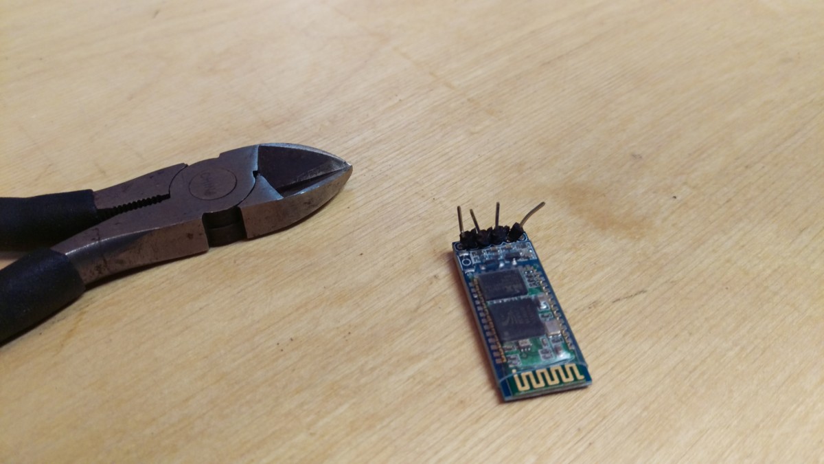
Use the smallest snips you have to separate the plastic
You need to separate the little plastic pieces, whatever they’re called, to get the 3 other pins out while leaving VCC in place. You could slide all 4 plastic pieces off of the pins, if you want. I find it easiest to grab some snips like the ones pictured, and simply clip them apart.
With the board held down, heat with the iron and pull with the pliers
After clipping them apart, I clamped the board to my bench. I used the soldering iron to heat the solder, and then used the pliers to pull it out. If you have desoldering wick, that’s even better. Use the iron to heat the solder, and let the wick suck it up. If I did this again, I would do it this way, because it will make the next step easier.
3 Pins in RXD, TXD, GND
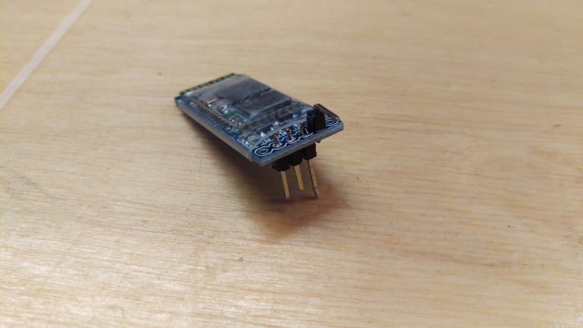
Same 3 pins on the other side – GND is much longer
Once the original pins are removed, we can put in pins of our own. You want them to go through the board, with the GND pin being one of the double-length header pins in the shopping list. The other two (TXD and RXD) can be normal length, like one of the many pins that ships with the components. As I said, if you used a desoldering wick earlier, the pins should now be nice and free of solder. If you didn’t, they’re probably full of solder, in which case you’ll have to do your best to heat the solder up while you ram the pin in with some pliers.
Putting a pin in VDD on the GPS module
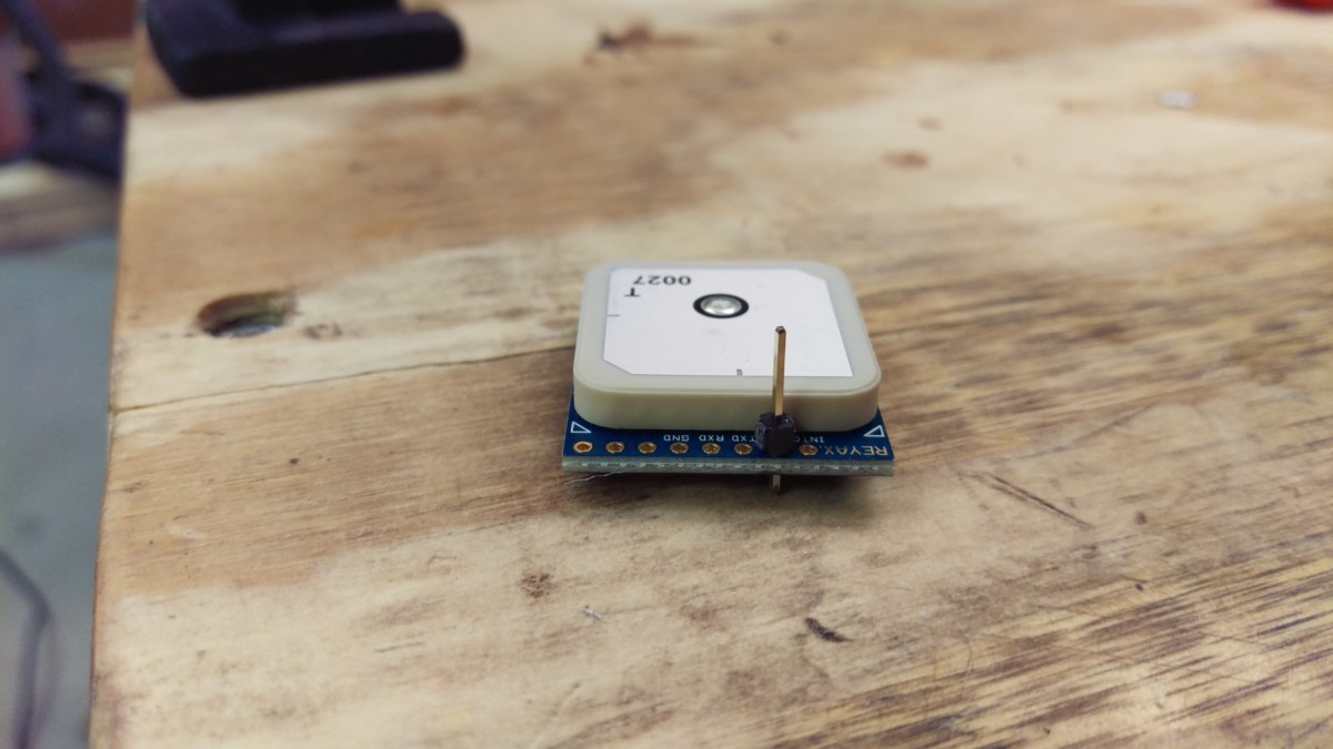
Pin for 5V Power in VDD
We’re nearly ready to hook the GPS and Bluetooth modules together. Before doing that, though, we should put a pin in the GPS module for 5V power while we still have easy access. This should be another double-length pin, with most of the length towards the bottom, so we can bend it to hook into the USB breakout module later.
Combining the Bluetooth and GPS modules
Stacking the modules
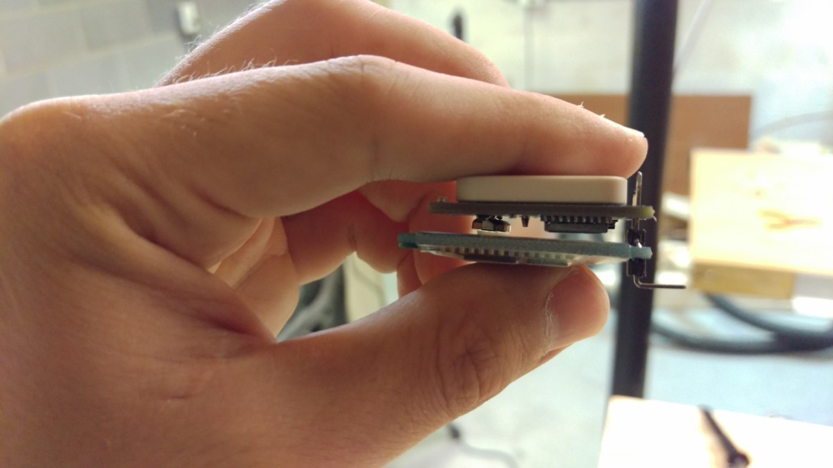
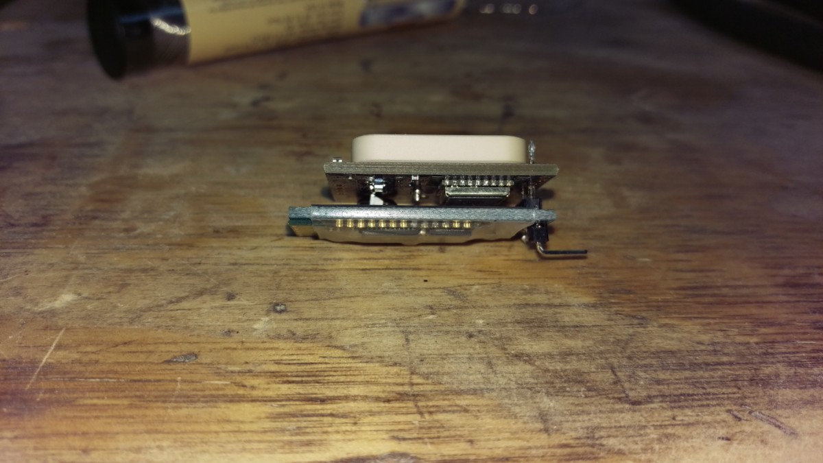
Side view showing clearance between the two modules
It just so happens that RXD, TXD, and GND on these boards line up so that we can just stack them as shown. The three pins soldered to the bluetooth module earlier will stick straight into the GPS module pins. As in the original diagram from earlier, RXD on Bluetooth goes to TXD on GPS, TXD on Bluetooth goes to RXD on GPS, and GND on Bluetooth goes to GND on GPS.
I also allowed a bit of a gap between them. Truthfully, they should also have a sheet of insulator as well, but I didn’t do that. Presumably You could still wedge something in there after soldering.
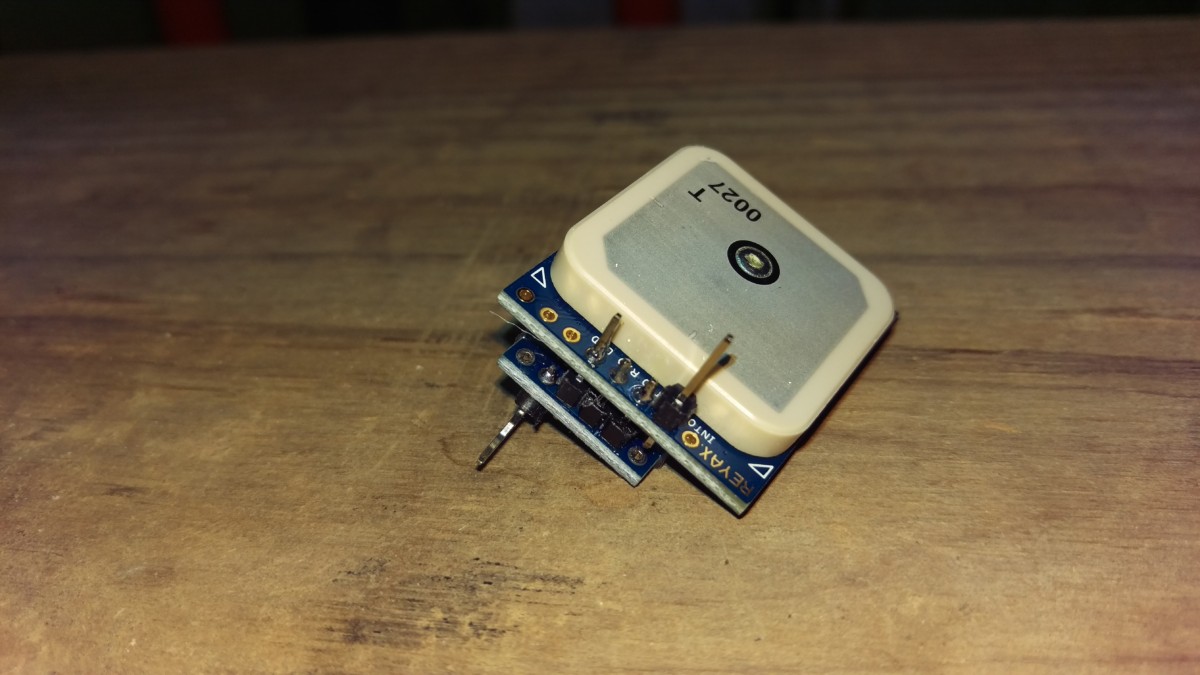
Both pieces combined
Once this step is complete, you’ll have something like the above. Notice the ground and +5V pins are quite a bit longer than the other two. That’s so we can hook them to the USB breakout module in the next step.
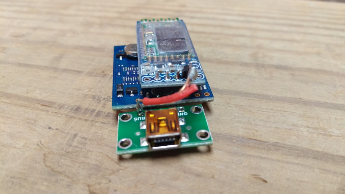
Hooking up the USB breakout module
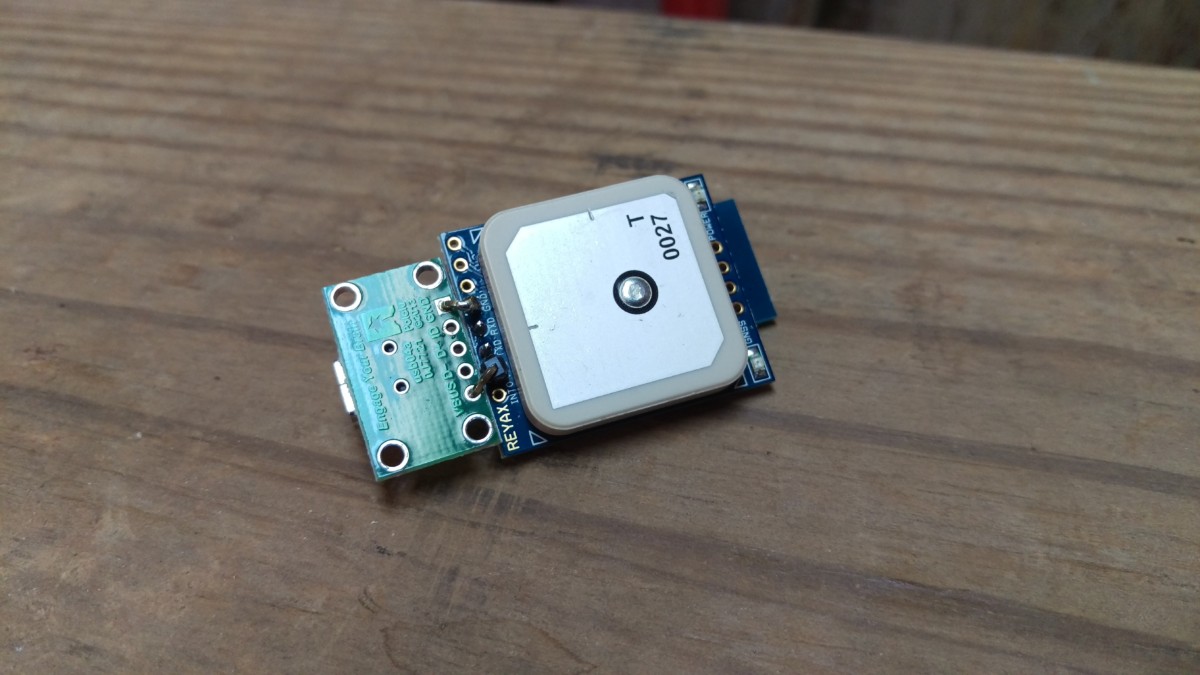
The USB module hooked up
The USB breakout module only has two pins we care about, VBUS (+5V) and GND (ground). The other pins are for data, and we are only using the USB cable for power. I simply bent the extra-long pins over with pliers until they would hold the USB breakout module where I wanted it, as shown. The GND pin was a little bit short, so I actually soldered extra pin to the board, bent that, and connected it to the original GND pin on the GPS module.
In any event, as long as the wiring looks like the above, it should work.
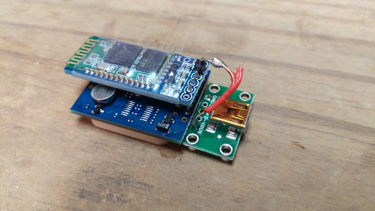
The Bluetooth module needs a 5V wire
Of course, the Bluetooth’s 5V module was on the wrong side, so it didn’t line up nicely. I simply took a short piece of 22 gauge wire and soldered it to the the top side of the USB breakout board, where the 5V pin sticks out. Then, I soldered the other end to the original VCC pin that came with the Bluetooth module. (The one that was not removed at the beginning of this article.)
Setting the GPS receiver to 10hz
Once the GPS receiver is ready, it still needs to be set to run at 10hz. By default, the module only does 1hz, which is no better than the average phone. I wrote up how to do this in a separate article.
Using the GPS receiver
To test it out, I used RaceChrono. It and Harry’s Lap Timer are the two most popular options, at least for Android. RaceChrono has a free version to try, though, while Harry’s doesn’t. To use it, simply add the HC-06 in your phone’s bluetooth menu like any bluetooth device. The default pin is 1234. (You can change this by hooking up a serial connection to the HC-06 and sending some AT commands, but I didn’t bother and this is out of the scope of this article.)
Then, in RaceChrono, go to “Settings”, “Device 1”, and change it to external GPS. Pick the HC-06 out of the menu. If you go back to the main screen and hit Start, it will connect to the GPS Receiver and the bluetooth light will turn solid red if you did everything right. You can hit the up arrow in the bottom left to see GPS details. Once it obtains a satellite fix, you should see the top right area show it is reading at 10hz. If it says 1hz, check that you didn’t goof something up.
Conclusion
Done
And there it is. Note that your phone or laptop won’t necessarily stay connected to it after pairing. I found that my phone didn’t actually connect until I opened RaceChrono, specified it as my external GPS, and actually started timing. In other words, it doesn’t bother connecting until something actually tries to communicate with the receiver. Once I did all of that, it worked perfectly.
In a future article, I’ll talk about making an enclosure for it. I am choosing to do something a little different than the 3d printed solution available on thingiverse.
[…] thingiverse page is that I went into a lot more detail on how to solder it up. Writeup is here: sub-$50 DIY 10hz Bluetooth GPS Receiver – Did It Myself I also wrote up how to set it to 10hz in detail: Setting Bluetooth GPS Receiver to 10hz – Did It […]
my version 🙂 17Hz gps hw >> https://photos.app.goo.gl/mh9Z3tBAqxCjDjNW6 <> https://photos.app.goo.gl/7n9ADc9mehHHwfodA https://photos.app.goo.gl/Q1mkFs2US82yZd2o9 << case
Nicely done, I like the 3d-printed case.
Hi
Nice project! Can I add this to the rest and have an accelerometer as well? Hi should I connect it?
Thanks!
https://rover.ebay.com/rover/0/0/0?mpre=https%3A%2F%2Fwww.ebay.com%2Fulk%2Fitm%2F221539755286
I have not done this, but you might be able to get away with an accelerometer with serial output, like this:
https://www.ebay.com/itm/MPU6050-Serial-6-axis-Accelerometer-Gyroscope-Module-for-Arduino/322763231536?hash=item4b26301130:g:vdcAAOSwCkZZOSYV
Then you would wire the accelerometer in instead of the GPS module.
As far as running an accelerometer AND a GPS module on the same bluetooth-serial adapter, that won’t work. The bluetooth module will connect to one serial device only. Also, this depends on whatever you’re using to connecting to the accelerometer supporting reading accelerometer data from a bluetooth-serial device.
Hi, thanks for the detailed writeup. It seems like the RY725xx series of GPS modules are now obsolete. Do you know if what I think the replacement RY825xx modules would work as a substitute?
REYAX RY825CF
http://reyax.com/products/ry82510/
https://www.ebay.com/itm/183150562491
Thanks!
Yes, that looks like it should work. Please let me know how it goes if you try it.
just ordered RY8253F 3v3 logic and flash RY825CF is 12v logic , have spoke with Reyax 🙂
Excellent, thank you for the tip! I’ll update the article.
Reyax send me by mistake CF module so can confirm thats wrong one 🙁 no comunnication (12v logic) aw replacment of 3F
HI James, thanx for the detailed info and what a great project. I want to try build one for my super bike track bike! I have assembled the parts and started testing. I can pair the bluetooth module and in Race Chrono it indicates that it is receiving data but no satellite info? I ordered the Reyax RY825CF gps module and requested the one with serial output and onboard flash? Any ideas? The gps is powered on and the red led starts flashing so its is seeing the satellites?
Unfortunately, if you read above comments, the RY825CF appears to be 12V, and the USB module in this article is providing 5V. I suppose you could try to get 12V power to it – your bike presumably has 12V, but be aware that you’d have to have a voltage regulator. Probably easier to buy the RY8253F instead, which can run on 5V.
To work like in the article, you need the RY8253F, which I’ve linked at the top of the article as well. Sorry for the confusion!
no both can be powered by 5v , but the logic in CF is 12v communication data TX RX , and HC05 HC06 communicate at 3.3v logic thats why RY8253F is required 🙂 recived replacment yesterday works at 17Hz no problem, baudrate have set up for 115200 https://photos.app.goo.gl/LPT4U36a95iunVLJ6
Ahh, OK – thanks for the clarification!
you can change title 🙂 for 17Hz 🙂 GPS Reciver see my photo https://photos.app.goo.gl/LPT4U36a95iunVLJ6
Nice!
What title to change to get 17hz?
Hi James, I’d like to build one of these myself for use while flying commercially. (I work for an airline) My question is if you know if I can use this with Google Maps on Android? That would be my preferred method but any mapping app that allows offline useage would be fine.
It looks like it should work, but it’s a little bit convoluted. You set it your phone to “use a mock location” and then install another app that sets the mock location to your external GPS’ real location. I haven’t tried this personally, but it looks like it would work.
https://nerdynerdnerdz.com/4053/pair-external-bluetooth-gps-receiver-with-android-for-superior-navigation/
Alternatively, any app that natively supports bluetooth GPS (like RaceChrono does) should work. Sorry I’m not more help, I’ve always just used my built-in GPS for navigation.
Thanks for the feedback. I will go ahead and try it. Basically I travel overseas a lot for work and would like to try to get the GPS position while on a plane using an android tablet. Generally the slow 1hz gps frequency in phones makes them notoriously difficult to get a lock because of how far you travel in that second.
That makes total sense. As noted above, it looks like the new part number for this GPS supports up to 17hz, in case you want to upgrade. I still mean to update my app to program it to 17hz, on my to-do list.
I’d be interested to hear if this works for you.
Hey man. Congrats for you project and the very detail tutorial. I will youse your tutorial to do a similar project, but I have some doubts.
First, I need change the GPS Module, because the model used by you is very dificult to find in my country. My ideia is use this gps (https://pt.aliexpress.com/item/32948172227.html?spm=a2g0o.cart.0.0.4dfc3c00iBUxGt , with NEO M7N). Do you think it meets the requirements?
Second, I will use the project in a kart, so I need create with a portable size. For this, I need include a source of energy, like a batery. Could you give me a tip for this?
Thanks,
Vinicius
Hi Vinicius,
It looks like this is probably only 1hz GPS: https://www.circuitspecialists.com/content/481525/NEO-6M-V2.pdf
Otherwise, it looks like it can probably be wired the same way, although I can’t say for sure without trying it. But you really want 10hz or better GPS update frequency.
Hi James
This link that I sent to you from Aliexpress sells 3 different models: NEO 6M, NEO 7M and NEO 8M. I will buy the NEO 7M model: https://www.u-blox.com/sites/default/files/products/documents/NEO-7_DataSheet_%28UBX-13003830%29.pdf
The model NEO 7M has 10hz update frequency.
Oh, I see. Very nice, much better deal than the reyax unit if it works then. It looks like it should work, but I can’t say for sure.
Regarding power for it, most drones use lipo batteries. I assume they would work for this as well, although they might be overkill. I don’t know enough about it to make any recommendations. I would ask someone into RC / drones.
Hey guys. I need help!! I bought all components and, before I solder all things, I connect all components with jumpers to test, but I have a problem and I don’t find the solution. I turn on the circuit, but the Bluetooth device don’t shows in the device list in my cell phone. I don’t know what to do. Can you help me? There is a configuration to do before?
Thank you!!
This is the photo from my test: https://ibb.co/vQrkYS9
Is the LED flashing? Flashing LED indicates that it is ready to pair.
Is this the first time you’re pairing with it? You may have to hook up a serial connection to the module to fix it.
The LED is flashing, like I saw in many videos on Youtube.
This is the first time that I try pair with my cell phone. I bought this component yesterday and this is the first time that I try use. I probably will buy a TLL component to do a serial connection.
I’m so sad because in your tutorail looks like so easy, and I don’t know what to do or try.
Yeah, that is a bummer. Do you have another phone/tablet/laptop you could try pairing with instead?
I try using 2 cell phones with Android and a PC with Wondows. No one of them can discovery the HC-06.
It is a bummer because all of videos and tutorials on web show that is very simple, almoust plug and play.
That is frustrating. I assume you also tried pairing with the GPS disconnected, just to make sure that isn’t causing a problem?
In any case, I don’t think I have any good suggestions, except that you can try a serial connection and maybe your HC-06 module is a dud. Sorry I can’t be more help, but good luck!
Also, you’re sure you’re getting a voltage to it within the tolerated range? If you have a variable power supply handy, you could try 3.3V instead of 5, just to see…
My first test was using only the HC-06, without the GPS. How didn’t work, I try add the GPS module to the circuit, and continous not working.
I will get a Arduino with a friend to connect and try change the setup from the HC-06. It is a try, but…
Hello, very usefull thank you, just some questions, you suggest to set the measurement period to 100ms so to have 10hz, ok, but what if I set 10 ms? 100hz? I think it’s no possibile so my question is: what is the limit? You suggest to use 10hz, Martin achieved 17 Hz, do you think is possibile something more? If no, why?
Thank you
Claudio.
The hardware is the limit, you can’t set it to anything you want. Older modules supported up to 10hz, while newer modules support up to 17hz.
Martin got 17hz with a newer module.
Thank you James for your fast replay, ok I got it, last question, do you think it makes sense try to use, instead of Reyax RY8253F, a Venus838FLPx-L?
https://altiforce.net/shop/prod-ic-gps-50hz-venus838flpx-l/
It’s a 50hz gps receiver, what Do You Think?
Thank you so much!!
That’s a standalone integrated circuit, so you’d have to design a board for it and SMD mount it. Based on the questions you’re asking, I would suggest sticking with the pre-packaged Reyax board.
Thank you James, thanks a lot
Hi guys,
i tried to build a similar 10hz GPS antenna (chips: GPS NEOM8-N + Bluetooth JDY-30). But i performed a factory reset through the U-CENTER interface. Now it never locks on any satellite.
Have you any suggestions?
Hello everyone, first I’d like to thank @James S. Spadaro for the very good tutorial.
As all of you already noticed, the GPS module used here is not available anymore, at least for me in Brazil. Then I decided to research an option and I found the NEO-7M module.
This module has the possibility to configure 10Hz of GPS position refreshing, and it already has a MicroUSB port, which means the supply voltage can be connected directly to it, the USB breakout board is not needed anymore. Check out my video presenting this module:
https://youtu.be/OLtj7QJKc7o
The Bluetooth module is supplied by the GPS module via the pins. The connection between them:
Bluetooth VCC——VCC GPS NEO-7M Module
GND——GND
TX———RX
RX———TX
Simple like that. Check out the videos demonstrating the assembling and the first tests:
https://youtu.be/cm_cItKuOvY
https://youtu.be/QHOXy8wTrTQ
Olá Yuri. Vi seus vídeos dos componentes e também vi um vídeo seu de kart com gráficos do traçado. Queria saber se deu certo usar esse NEO-7M no kart. Tem uma precisão boa? Você usou para cronometragem também?
olá amigo, tentei fazer a configuração para 10hz e o aplicativo não consegue fazer a configuraçao, voce pode me ajudar?
hello friend, I tried to make the configuration for 10hz and the application cannot make the configuration, can you help me?