K24 Swap – Steering Rack and Subframe
After removing the Miata engine, you can prep the engine bay for the new K24 motor. This is a straightforward procedure that involves swapping the subframe for the KMiata / V8Roadsters replacement, as well as putting in a depowered NB steering rack. Swapping the steering rack and subframe is one of the easier parts of a K swap.
See All K24 Swap Articles: K24 Miata Swap Main Page
Parts Required
- KMiata Subframe (A V8Roadsters-sourced part)
- NB Depowered Steering Rack
Preparing the NB Rack

NB rack, mounting bolts, and lower column section
Even though this swap is on a 97 Miata, you must use an NB Miata (99-05) steering rack. The NB rack has the correct mounting holes for the V8Roadsters subframe. It plugs right in to the NA Miata steering wheel and tie rod ends.
The picture shows a properly depowered NB rack, mounting bolts, and a lower column section. You need all of these parts off of an NB car to complete the swap. You must properly depower the rack to fit it under the engine. There are several folks online selling depowered racks ready-to-go.
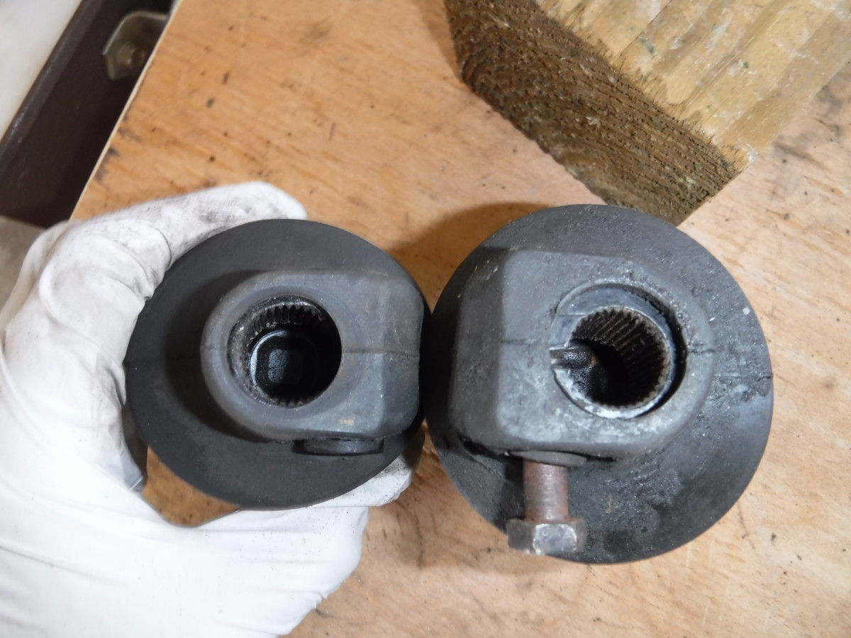
NA left, NB right
When I say lower column section, I’m talking about this piece. This connects the steering wheel column to the rack. They’re identical on the side connected to the column, but the end connected to the NB rack has a larger diameter.
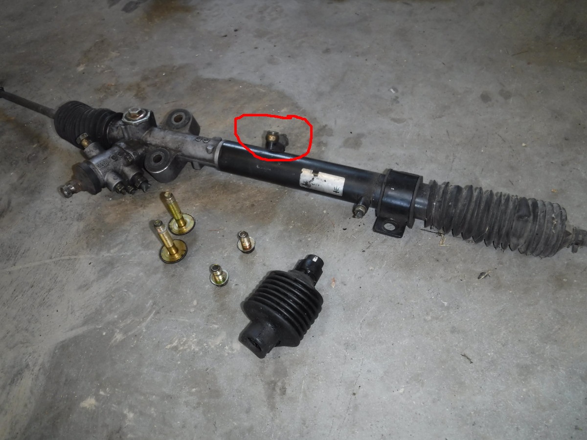
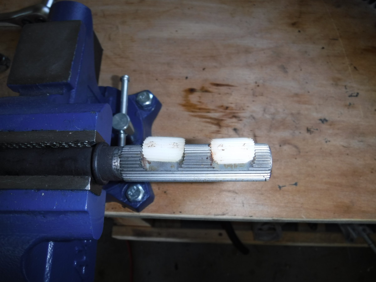
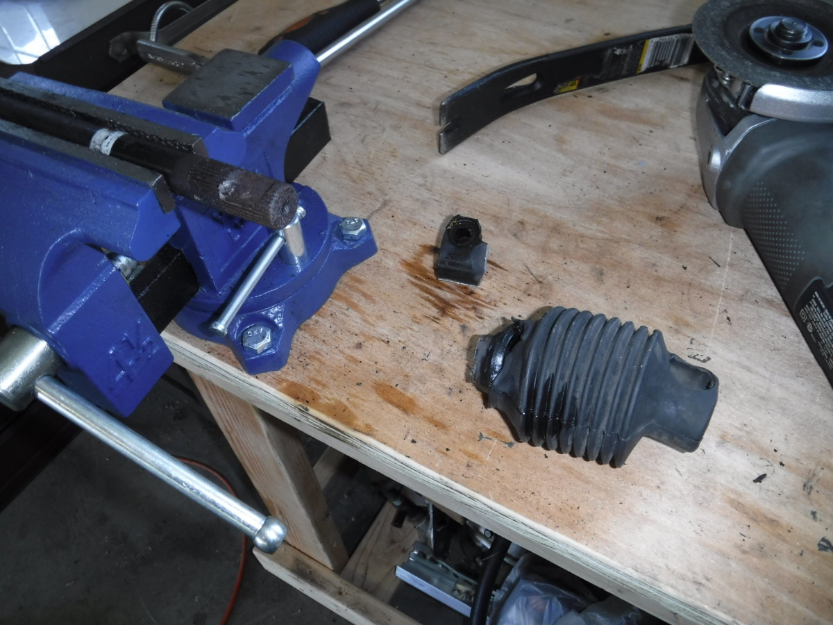
The input ports must be removed entirely
You have to completely remove the input ports on the rack, unlike with a “normal” depower. In other words, the ports circle in red in the picture. They interfere with the KMiata oil pan.
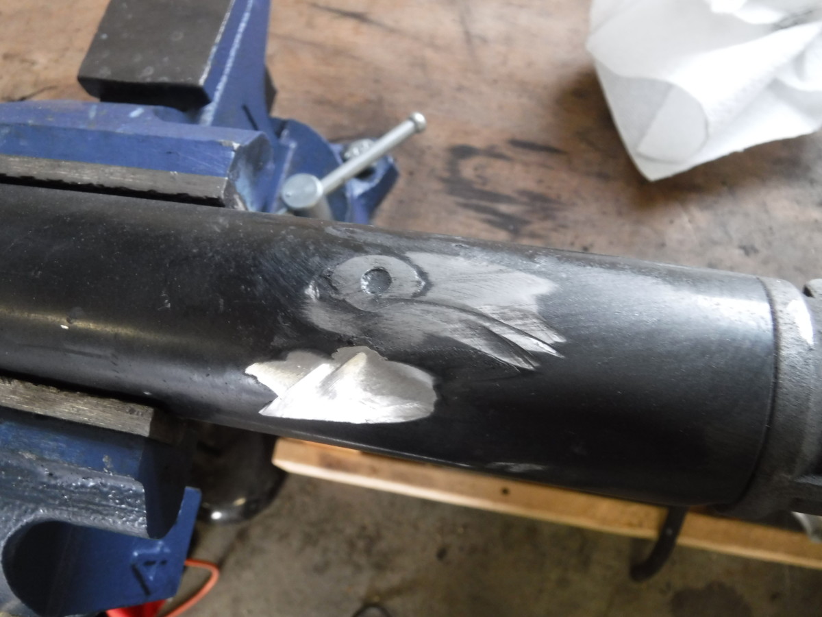
An angle grinder can zip these off and sand the shaft smooth
An angle grinder


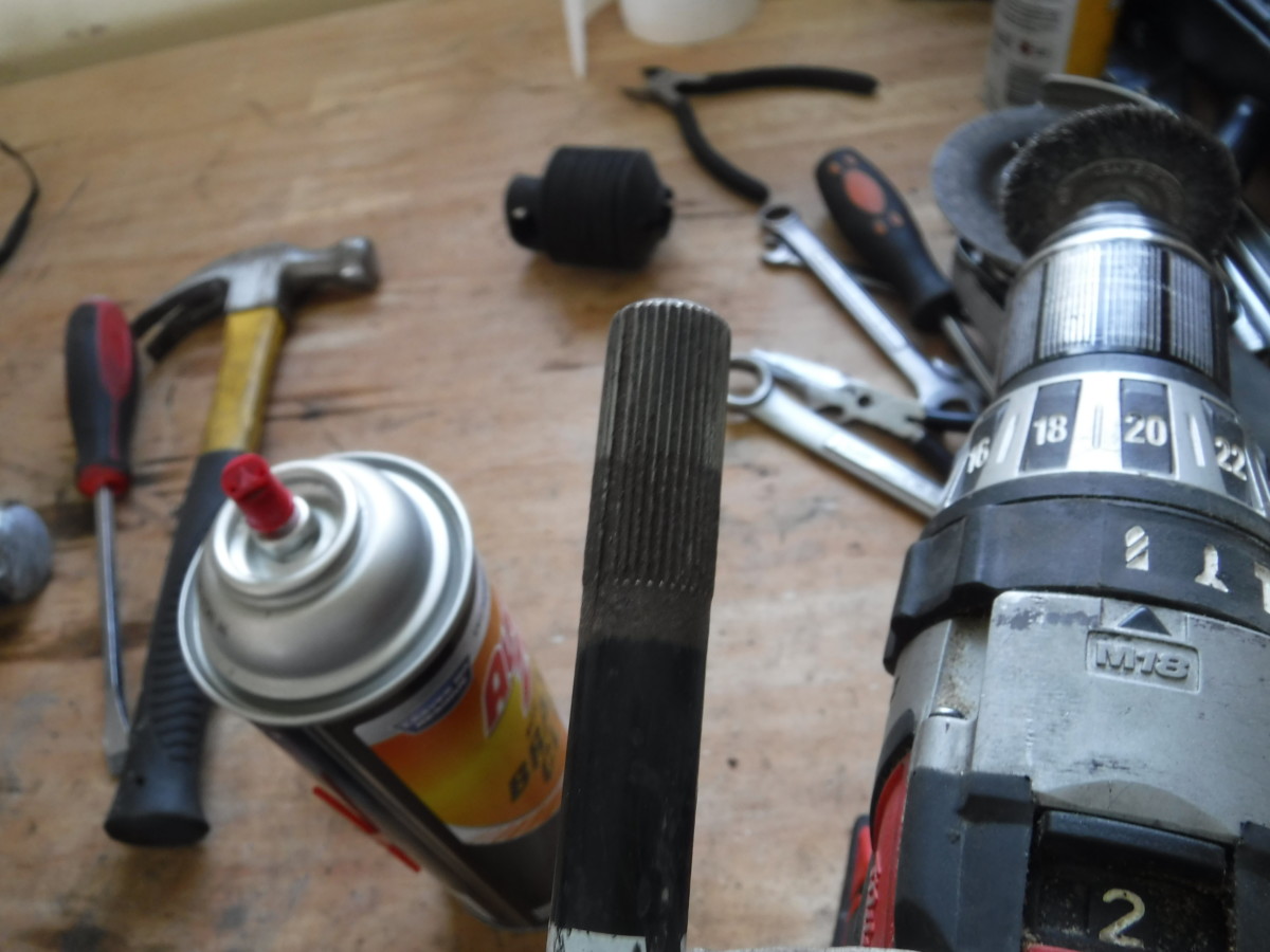
Additionally, I put some Permatex Ultra Black RTV
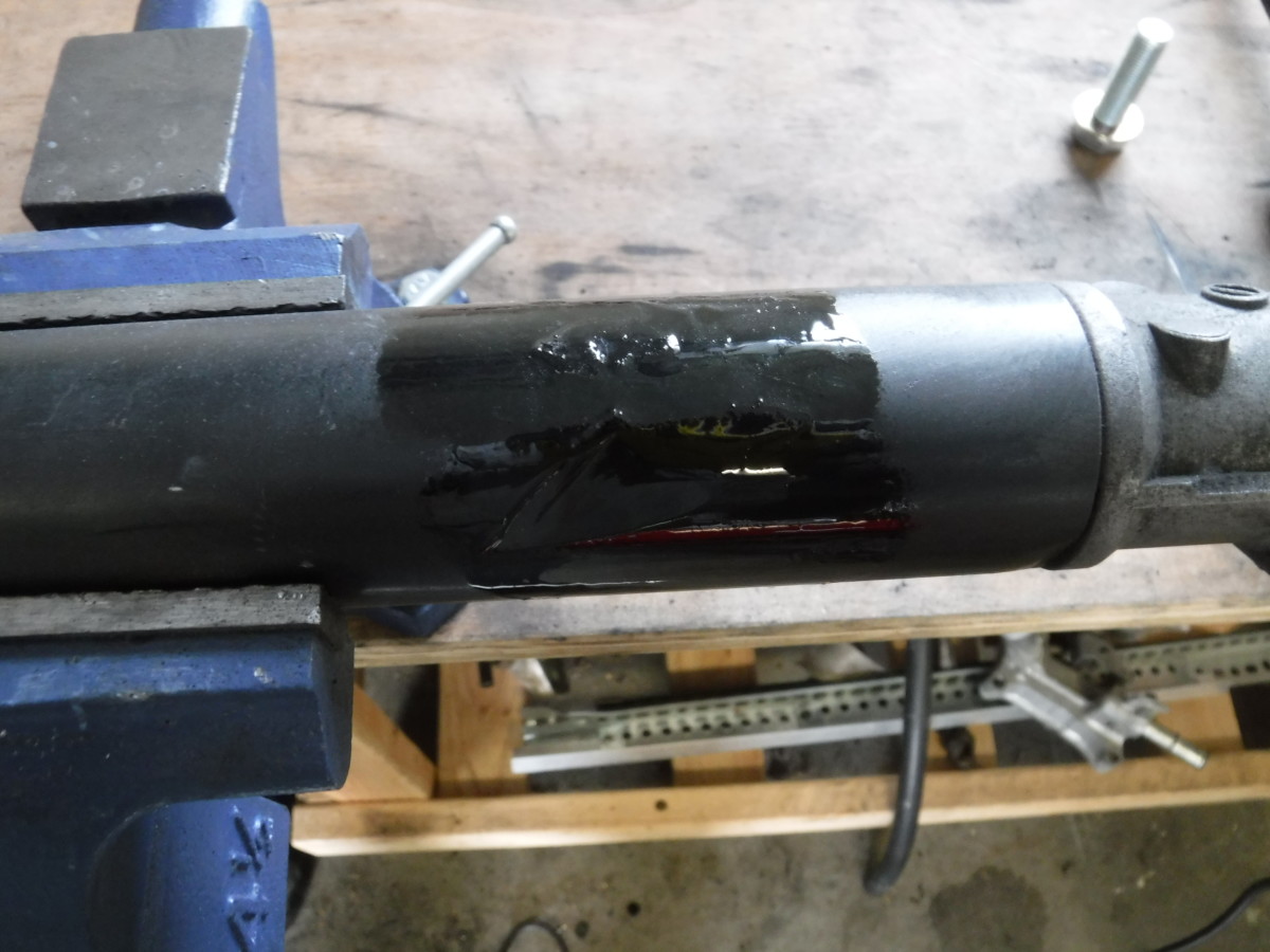
Hit it with black primer and paint

Done
Once the RTV was dry, I applied some black 2-in-1 primer plus paint. This rack is ready to put in the car.
Unhooking the Tire Rod Ends
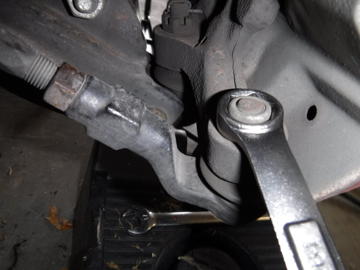
Tie rod end nut
Zoomed out view for perspective
After removing the nut
Before the old steering rack will come out, you must unhook the tie rod ends from the wheel hubs. They each have a single nut on top, which may have a cotter pin in it. Mine do not. It helps to lock the steering to get leverage on this nut.
Tie rod end puller

Removed
Once the nut is off, you need to press the tie rod end out of the spindle. Because these are in fairly tight, it helps to use a tie rod end puller

Removing the Old Steering Rack
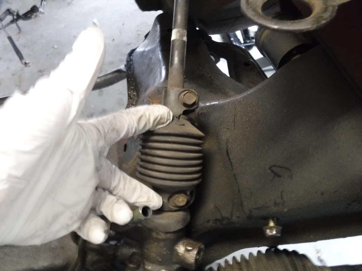
These bolts hold the column section to the rack and column
With the tie rod ends disconnected, you can loosen the column section next. This universal joint holds the steering column to the steering rack. The two bolts in the picture clamp everything down, so I went ahead and removed both of them.
Left Steering Rack Bolts
Right Steering Rack Bolts
After removal
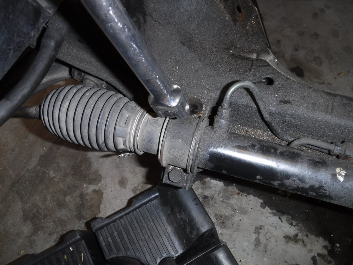
Four bolts hold the steering rack to the subframe. Once these bolts are removed, the steering rack drops right out.
Removing the Lower Column Section
This was not my lucky day
If you’re lucky, the lower column section will come off of the steering column easily. However, since rust and corrsion have likely set in, it probably won’t. In this case, you can do like I did and pull out half of the steering column as shown.
Note: Removing the intermediate shaft like this (and then losing the little white pieces) can add slop to your steering. If your intermediate shaft is rusted to the steering rack, that’s unfortunately the only way for it to come out. You can buy a new intermediate shaft instead, although this will require removing your steering column from inside the car to install through the firewall.
These will never go back in
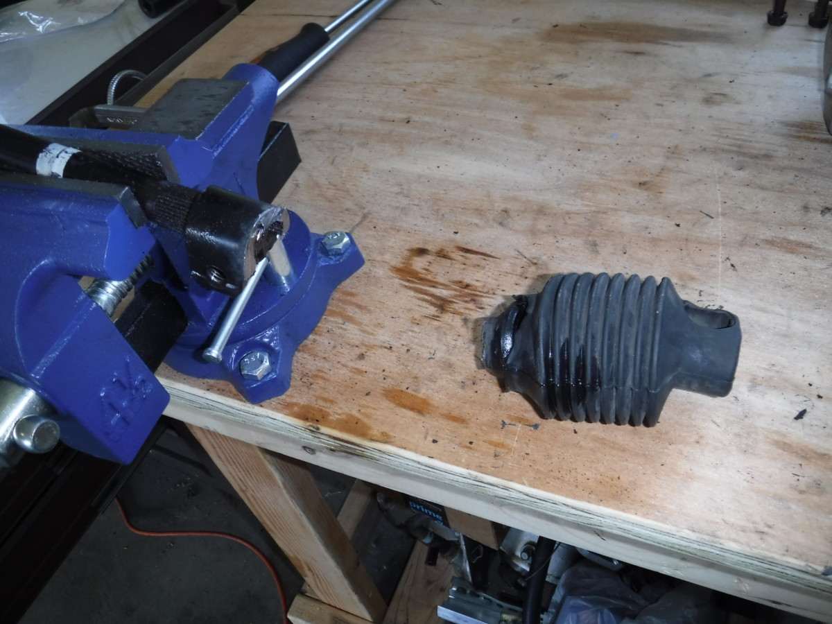
Unfortunately, the column section has these two white plastic inserts that will never go back in the car. After some googling, it appears these exist to keep gunk out of the steering shaft. I left them out, but you can retain them and try to reinstall them if you want.
Ended up having to cut off the lower column section
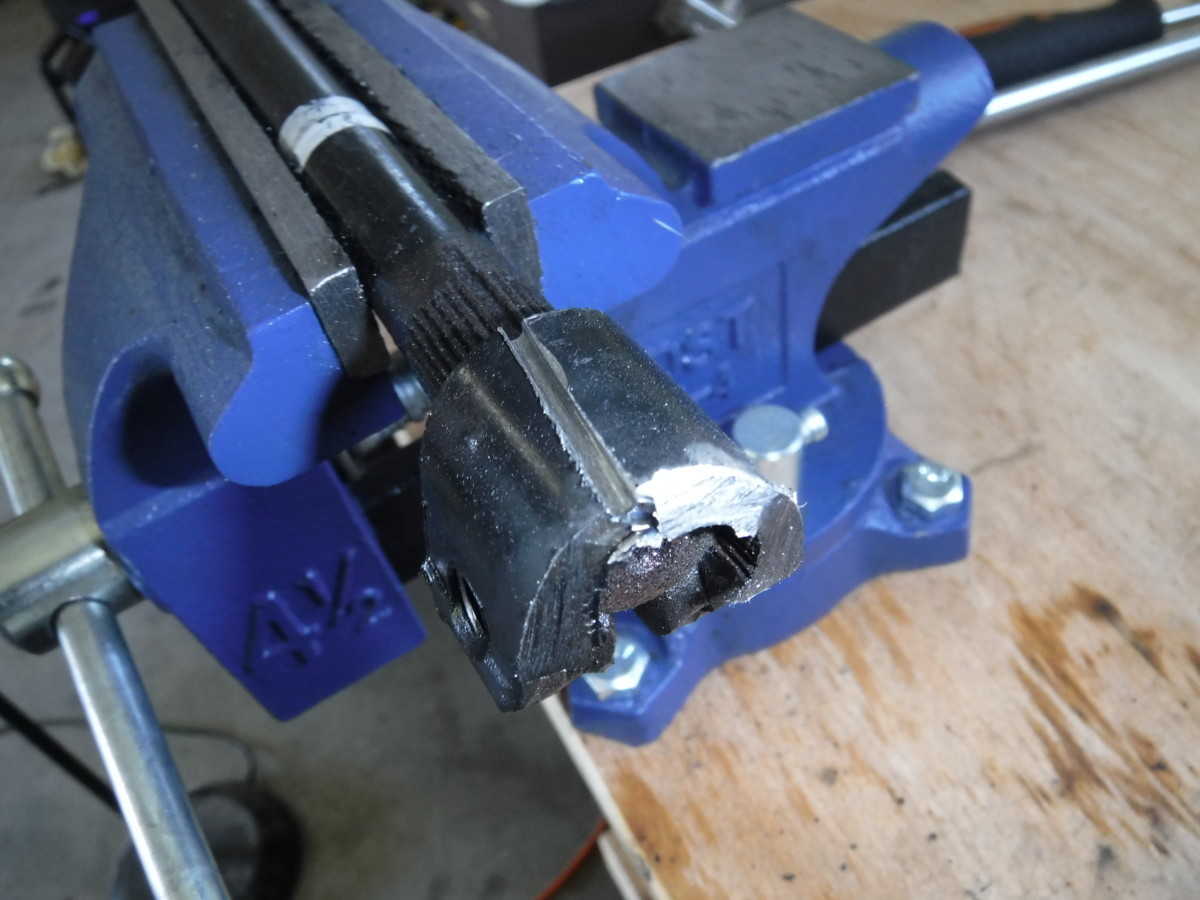
Carefully scored along length
Came right apart with pliers
I had difficulty removing the lower column section, even using a hammer and a vise. My angle grinder with a cutoff wheel quickly lopped the section off altogether. A final scoring cut made the remaining piece easy to pry off. Of course, this method will destroy the lower column section, in case you planned to reuse it for anything.
The shaft after cleaning with a wire brush and brake cleaner
Some brake cleaner

Attaching the New Lower Column Section
NA left, NB right
You can now put the new lower column section on. Again, you need to use an NB lower column section. The side that goes into the steering column shaft is the same between the two, but the NB section has a larger diameter hole on the steering rack side, as pictured.
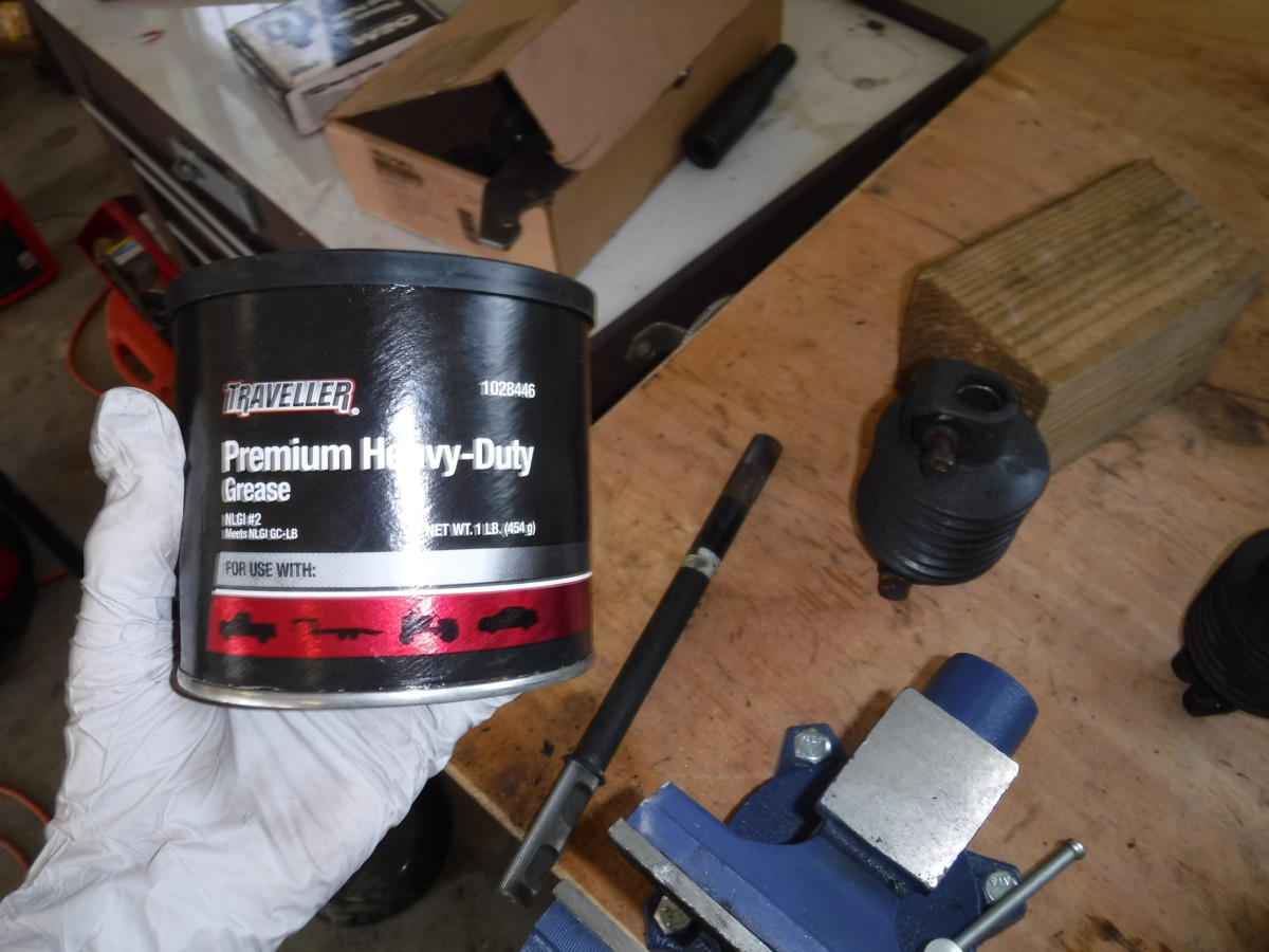
Some axle grease on the splines
I put some axle grease on the splines to help the new lower column section slide on. This should also help prevent corrosion if it has to come apart again in the future.
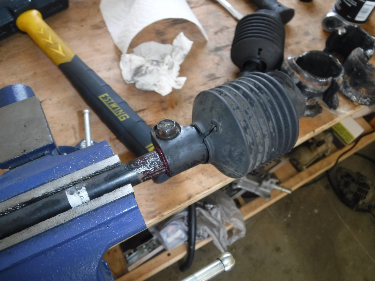
After tapping it on with a hammer
Finally, with the shaft still in the vise, I tapped the lower column section on with gentle taps from a mini sledge hammer
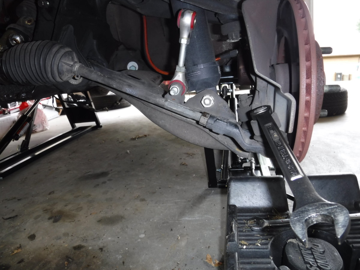
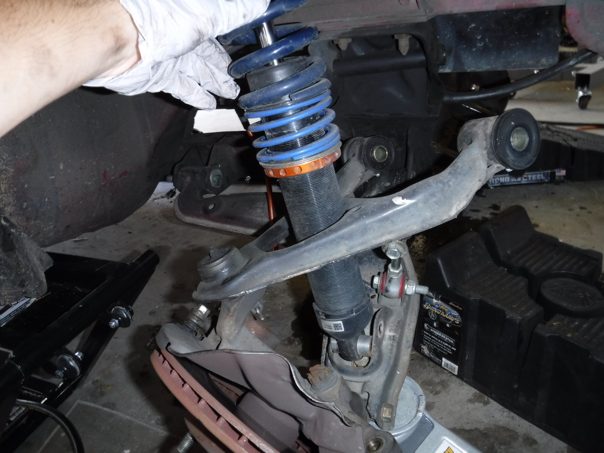
Detach the Wheel Hubs from the Old Subframe
Unbolting the two OUTER coilover bolts
The resulting droop
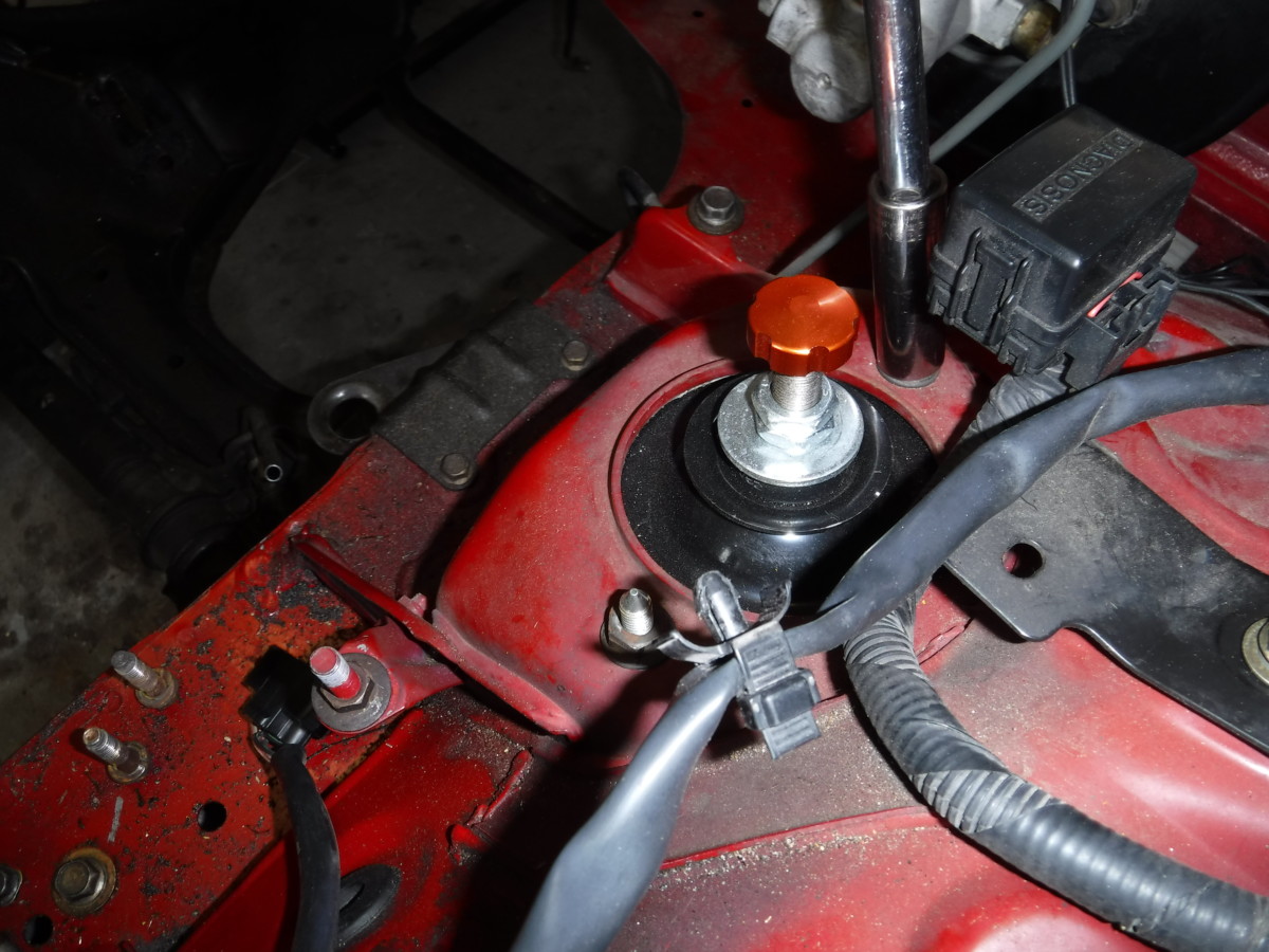
Now the subframe needs to be replaced before the new steering rack goes in. I chose to unbolt the coilovers from the fenders. By doing this, the wheel hubs won’t hang by the coilovers when the subframe is out. This may not be necessary, I’m not sure. Note that if you do this, you remove the OUTER two nuts on the fender. The large central nut holds the coilover together and should not be removed.

The UCA long bolt can come out next
The long bolt after removal
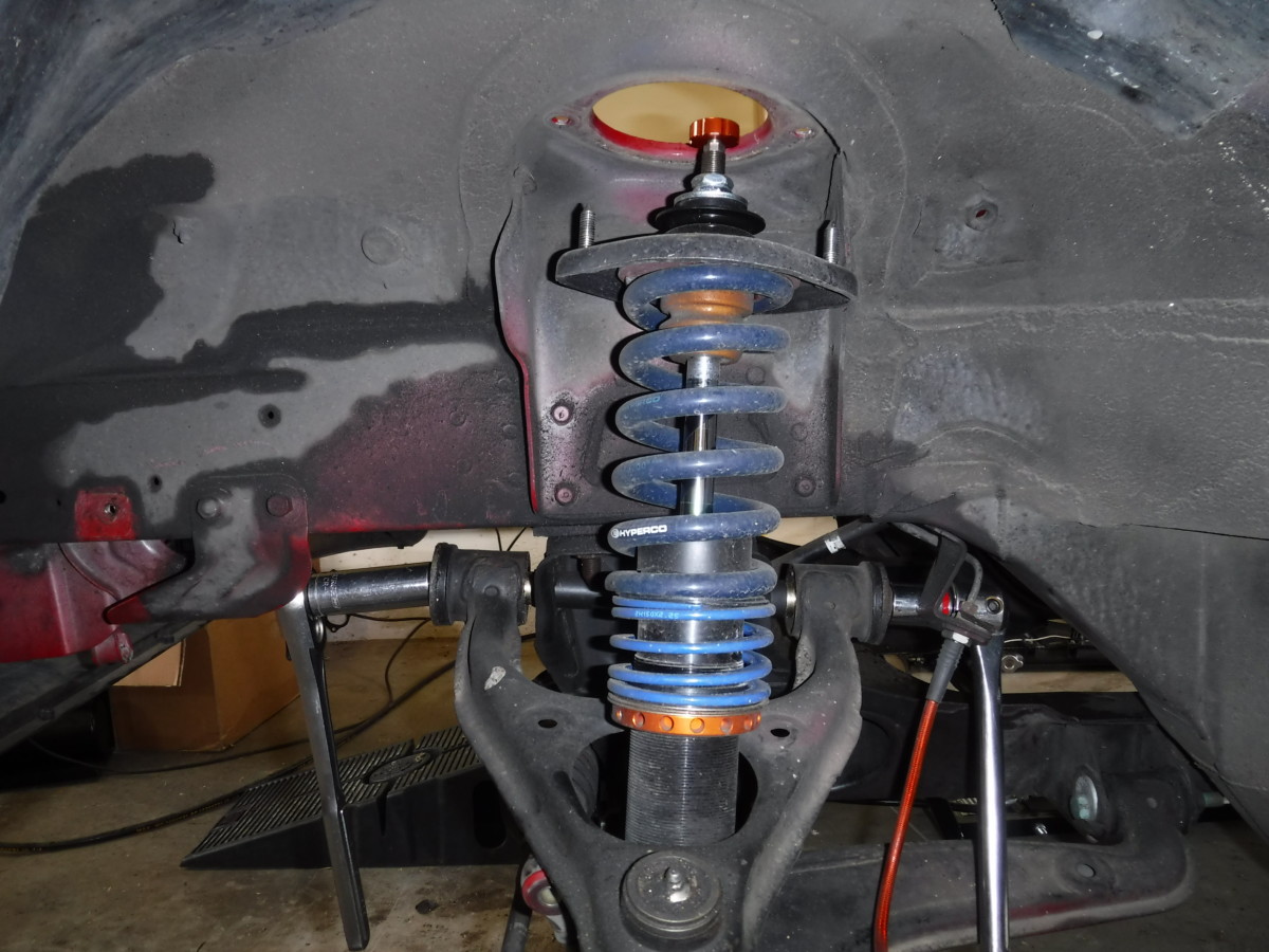
The upper control arm long bolt can be removed next. This foot long bolt holds the upper control arm to the old subframe.
It may be easier to simply remove the coilover
With the lower mounting bolt removed, it lifts right out
With the UCA long bolt out, the coilovers come right out after unbolting the bottom shock mount. This is optional but gets them out of the way.
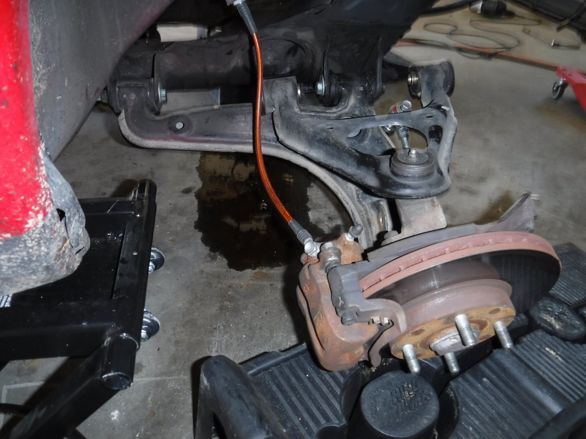
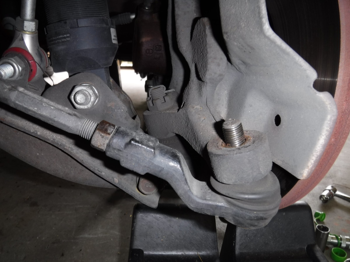
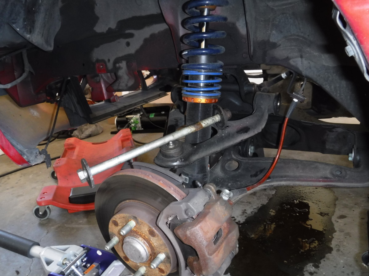
The LCA is the only thing holding the wheel hub to the subframe
At this point, the lower control arm is the only thing holding the wheel hub to the subframe.
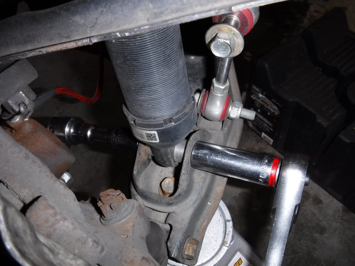
Front bolt
Rear bolt

Removed
Before the next step, I placed some ramps under the wheel hubs to support them. Two more bolts hold the lower control arm to the subframe. Once these are removed, the wheel hub is entirely detached aside from the brake line.
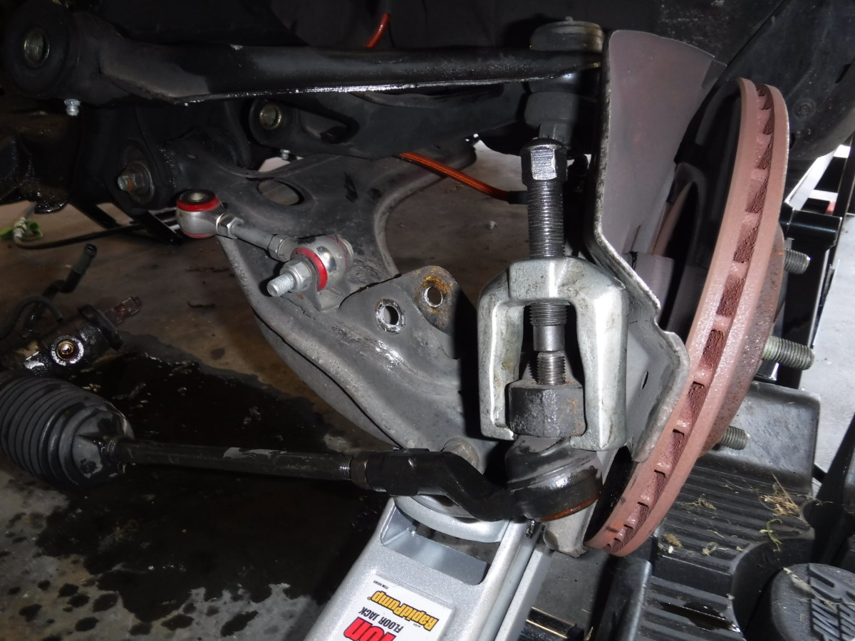
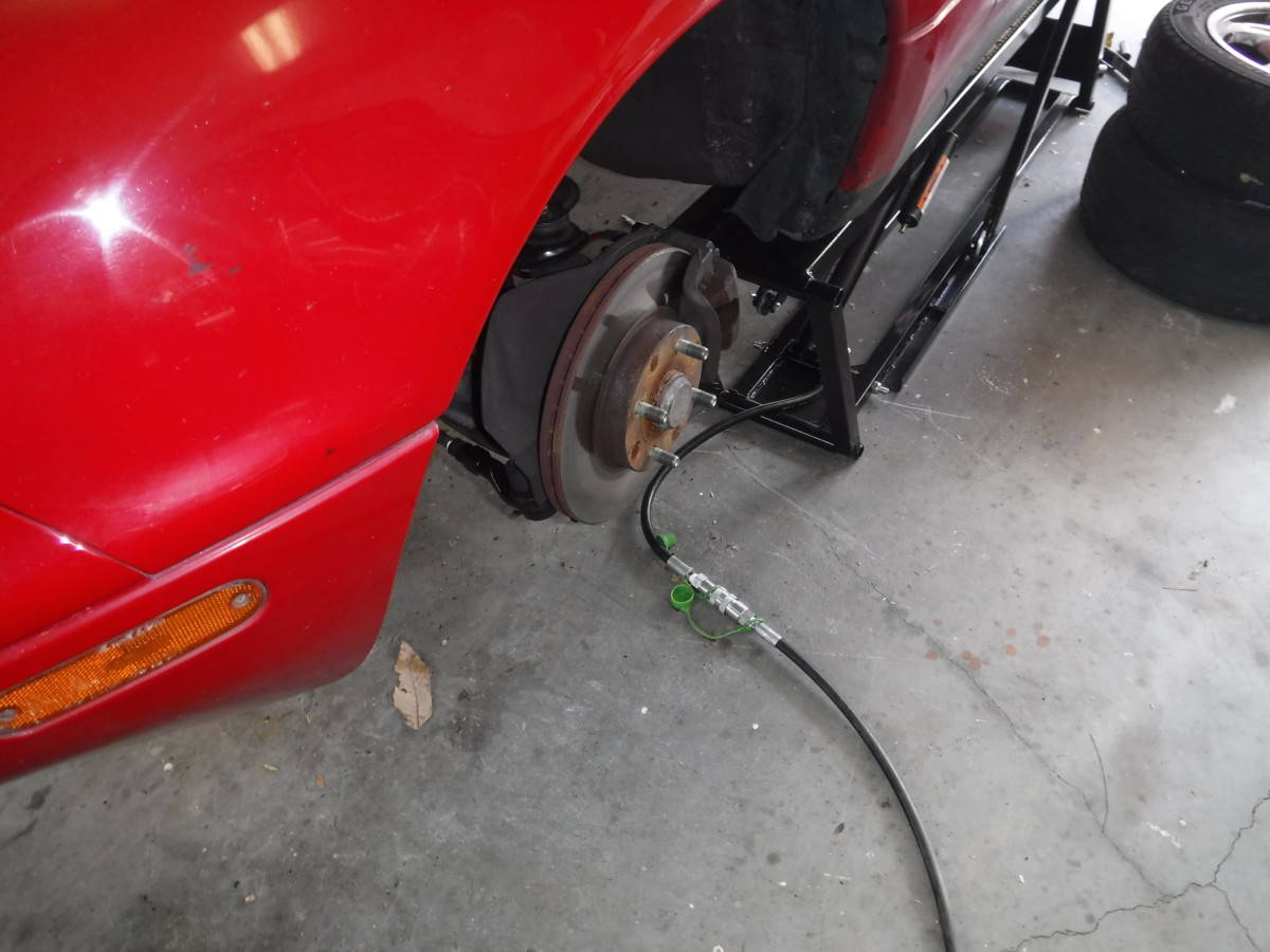
If you want to remove the brake line, you can pull the hub entirely out of the way. I didn’t want to have to deal with the mess, so I left mine connected. If you leave them connected, make sure you support the hubs so there is no strain on the lines.
Detach the Charcoal Canister Hose
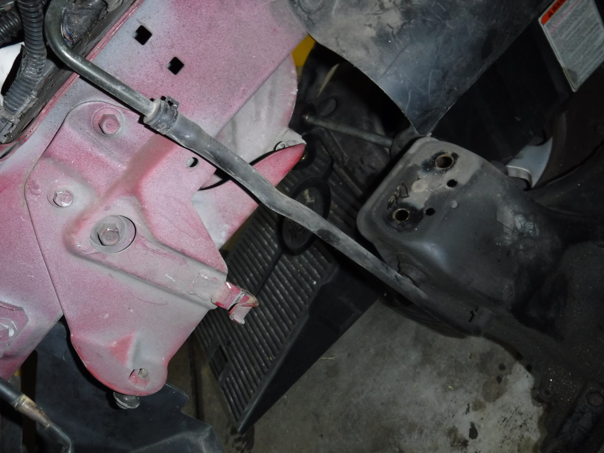
NA cars have this charcoal canister hose to the old subframe
NA Miatas have this hose from the charcoal canister into the subframe. This needs to be detached from the subframe using some channel lock pliers
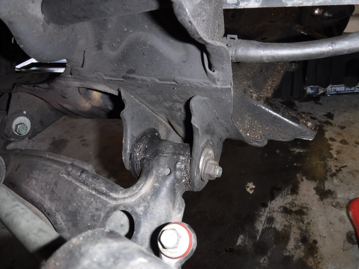
Remove the Old Subframe

Rearmost Bolt
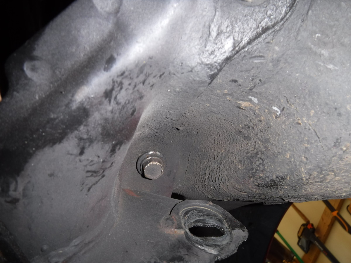
Further Forward bolt
At this point, the subframe should have nothing connected to it, so you can now unbolt it. There are eight bolts total. The two bolts pictured can be removed from the rear of the subframe on each side.
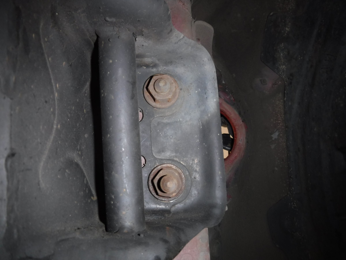
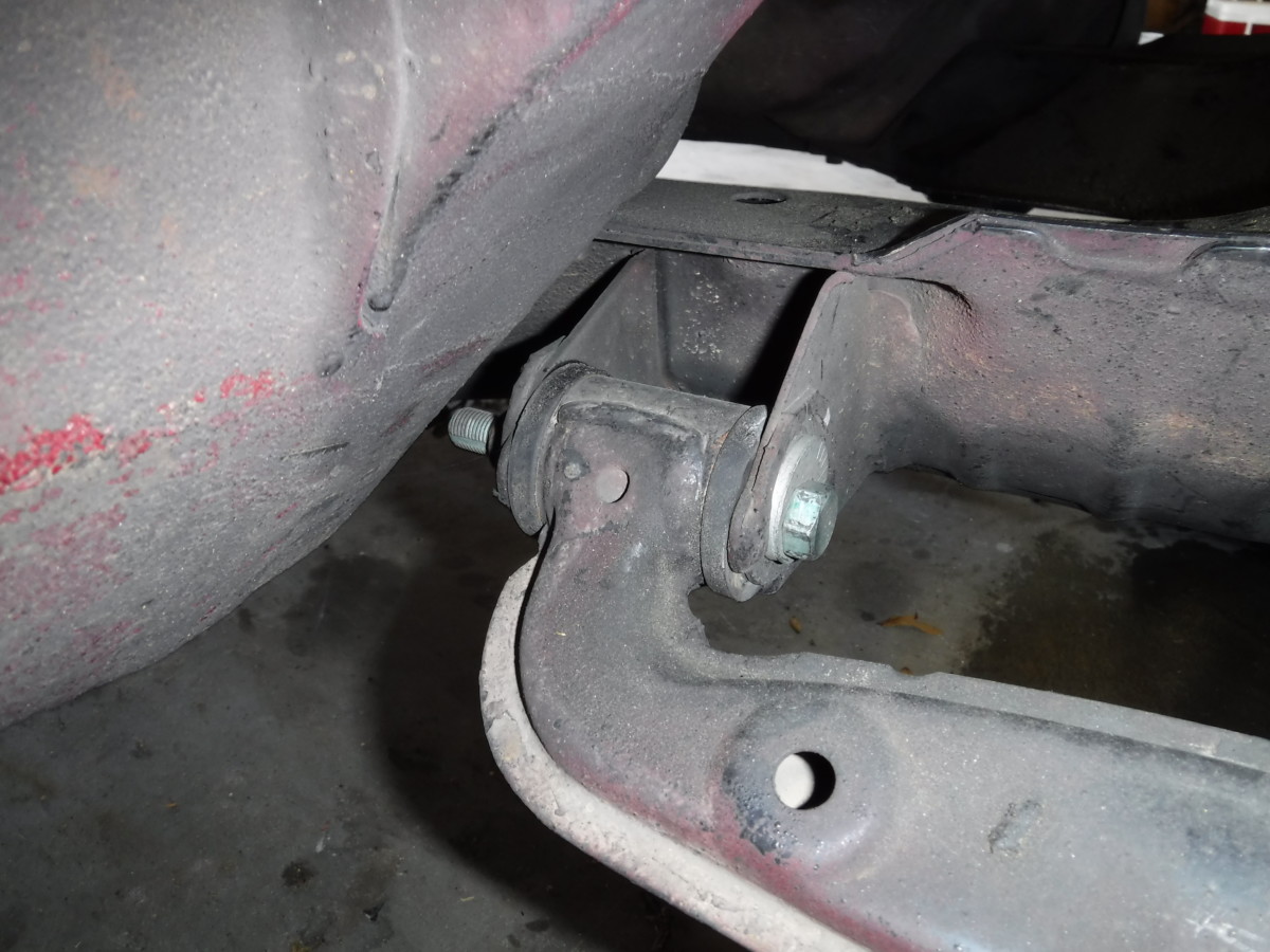
These are the main nuts for the subframe
Another perpsective shot
The four main nuts shown are left, two on each side. I broke them loose next using my 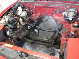 _bm_tl” href=”http://www.amazon.com/Kobalt-120-Volt-Corded-Impact-Wrench/dp/B004Q03WLY/ref=as_li_bk_tl/?tag=diditmyself20-20&linkId=08c7d951339c514019eb0e2b1097e99c&linkCode=ktl” target=”_blank” rel=”nofollow noopener” data-amzn-ps-bm-keyword=”impact wrench kobalt” data-amzn-link-id=”08c7d951339c514019eb0e2b1097e99c”>impact wrench
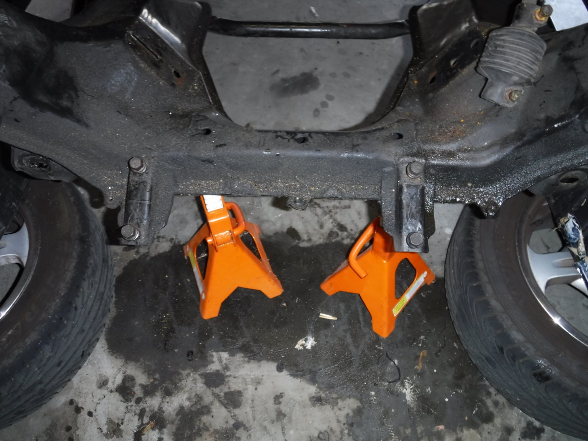
Jack stands to help support the subframe
With all four bolts loose, I put some jackstands under the subframe to help support it. With the subframe supported, remove the four bolts, and it will come free. Having a friend to hold the subframe while you remove the bolts makes this easier. The old subframe is about 33 pounds, so you probably don’t want it to fall on you. Then again, I don’t know how you live your life.
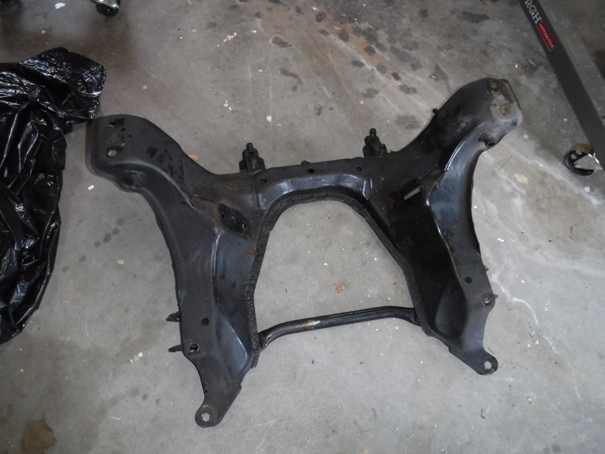
Old subframe out
Once that’s out, you’re ready to install the new one.
Installing the New Subframe
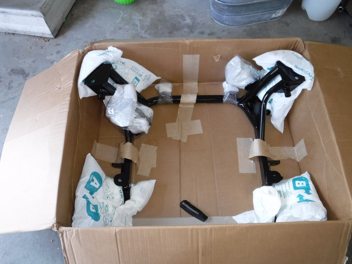
V8Roadsters subframe new in box
The new subframe ships in a big box with lots of cardboard.
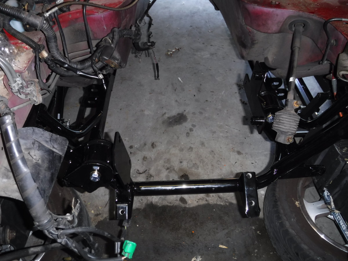
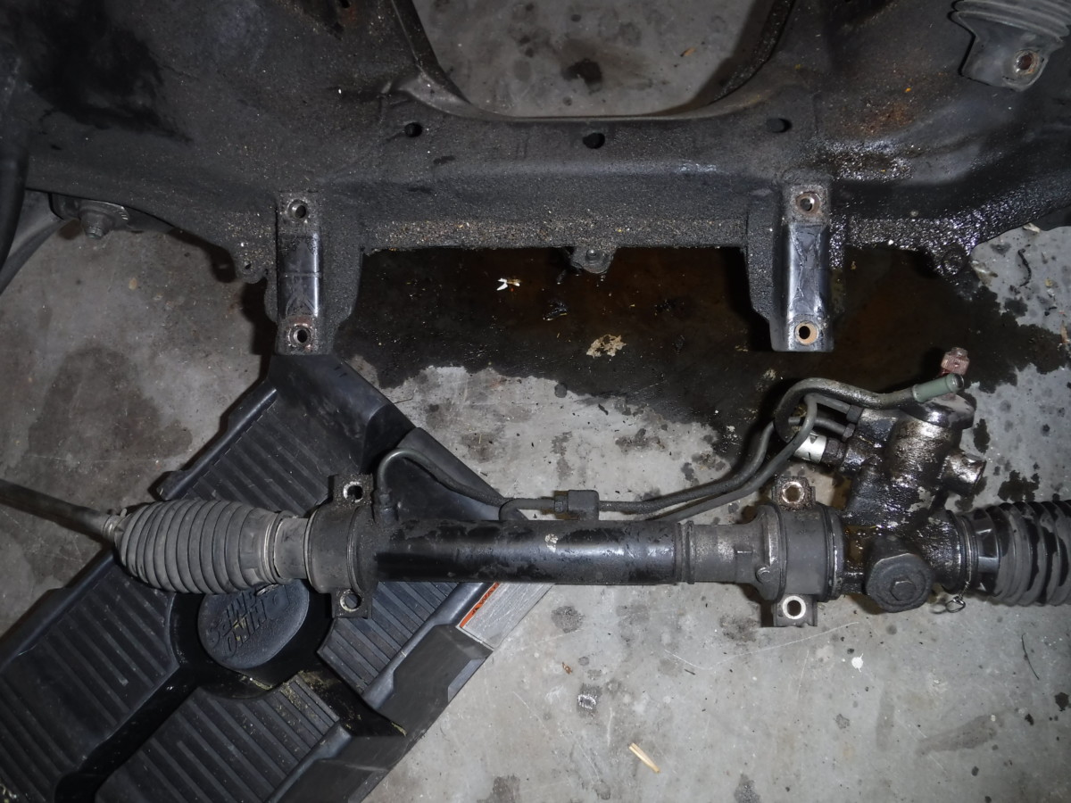
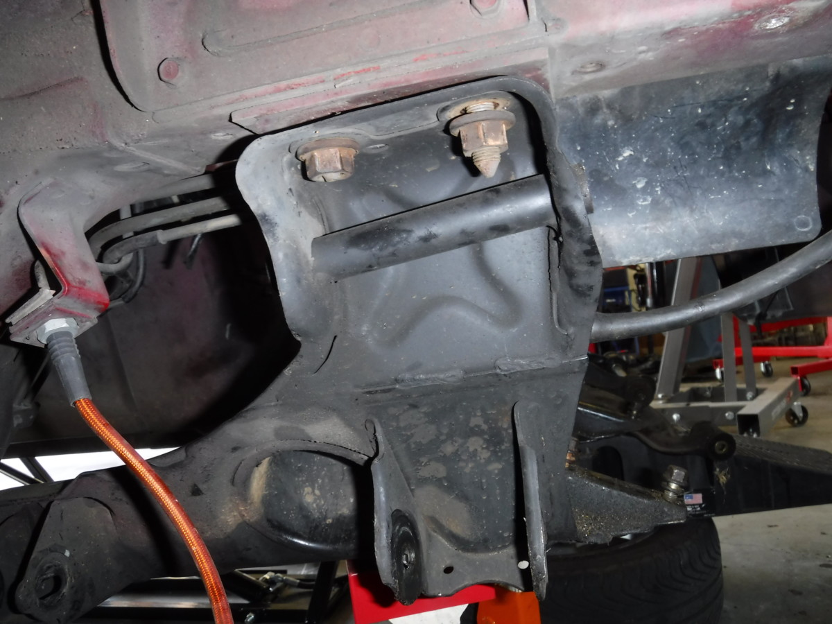
Bolts right up in place of the old one
The new subframe is about 30% lighter than the old one. Thanks to its tube frame, it’s also a great deal less cumbersome. Installation involves holding it up, with a helper if necessary, and reinstalling the four main nuts from before.
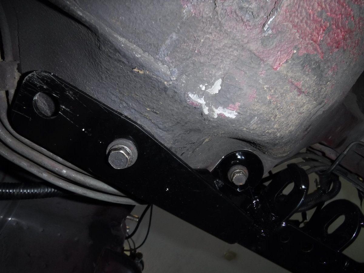
From one side, the main nuts supporting it
Here are two of the four main nuts reinstalled.
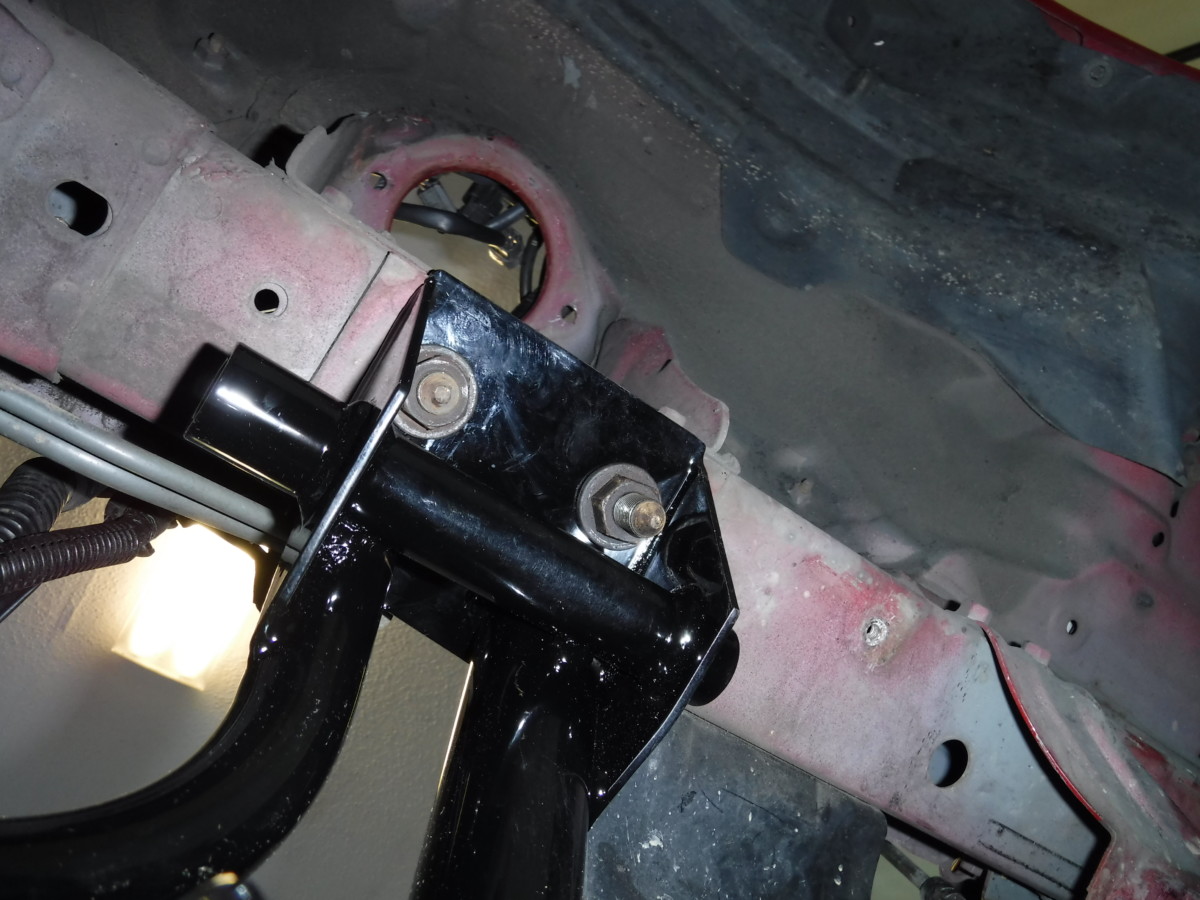
Rearward supporting bolts
The four bolts to the rear also go right back in. There’s a large hole towards the back that appears to be for a different year car. I left it alone.
Torque the main nuts to 69-86 lb-ft, while the four smaller bolts get 51-61.
Reinstall the Wheel Hubs
I didn’t take pictures, but this is the reverse of removal. Reinstall the lower control arm into the new subframe’s mounts and torque to 69-83 lb-ft. Then reinstall your coilovers, torquing the lower shock mount to 54-68 lb-ft. The UCA bolt gets 87-101 lb-ft, and then the small coilover shock tower mount nuts are only 22-26 lb-ft.
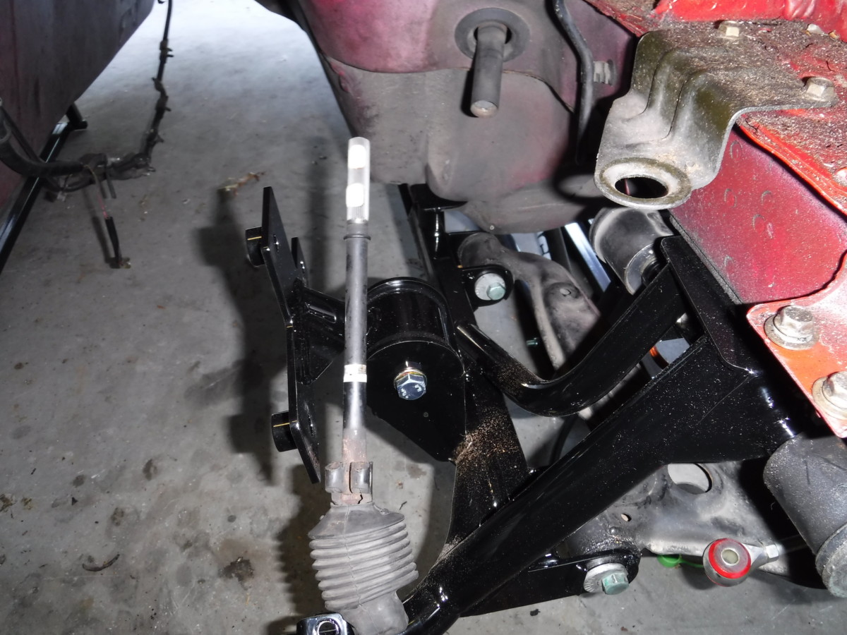
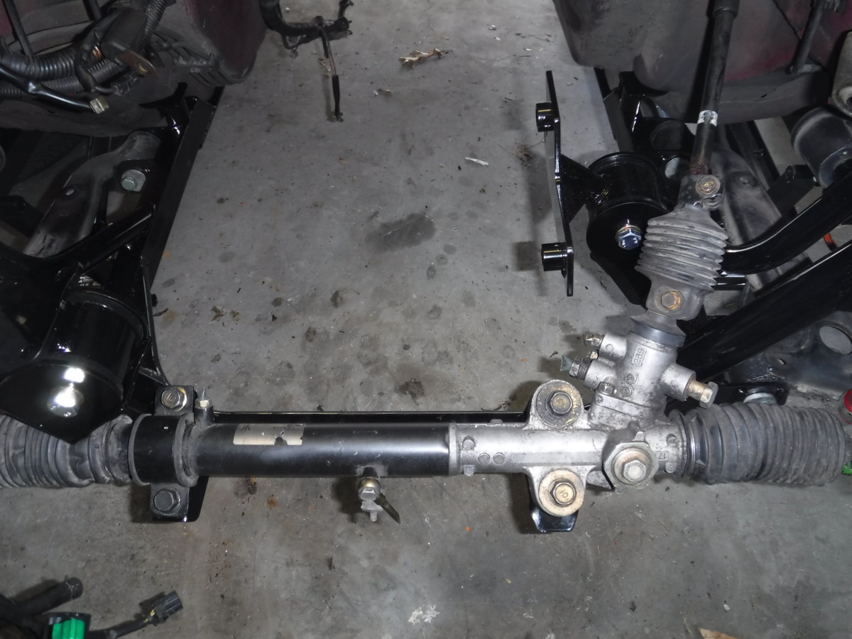
Reinstalling the Steering Rack
I couldn’t get the steering column section back in with the plastic tabs

Ended up leaving them out
Once the subframe is in, the rack goes back in very easily. First, I reinstalled the lower column section. As stated earlier, it was nearly impossible to reinstall this with the white plastic tabs, so I left them out. I pushed the column section up as far as it would go, so the black rubber o-ring is pushed out of sight.
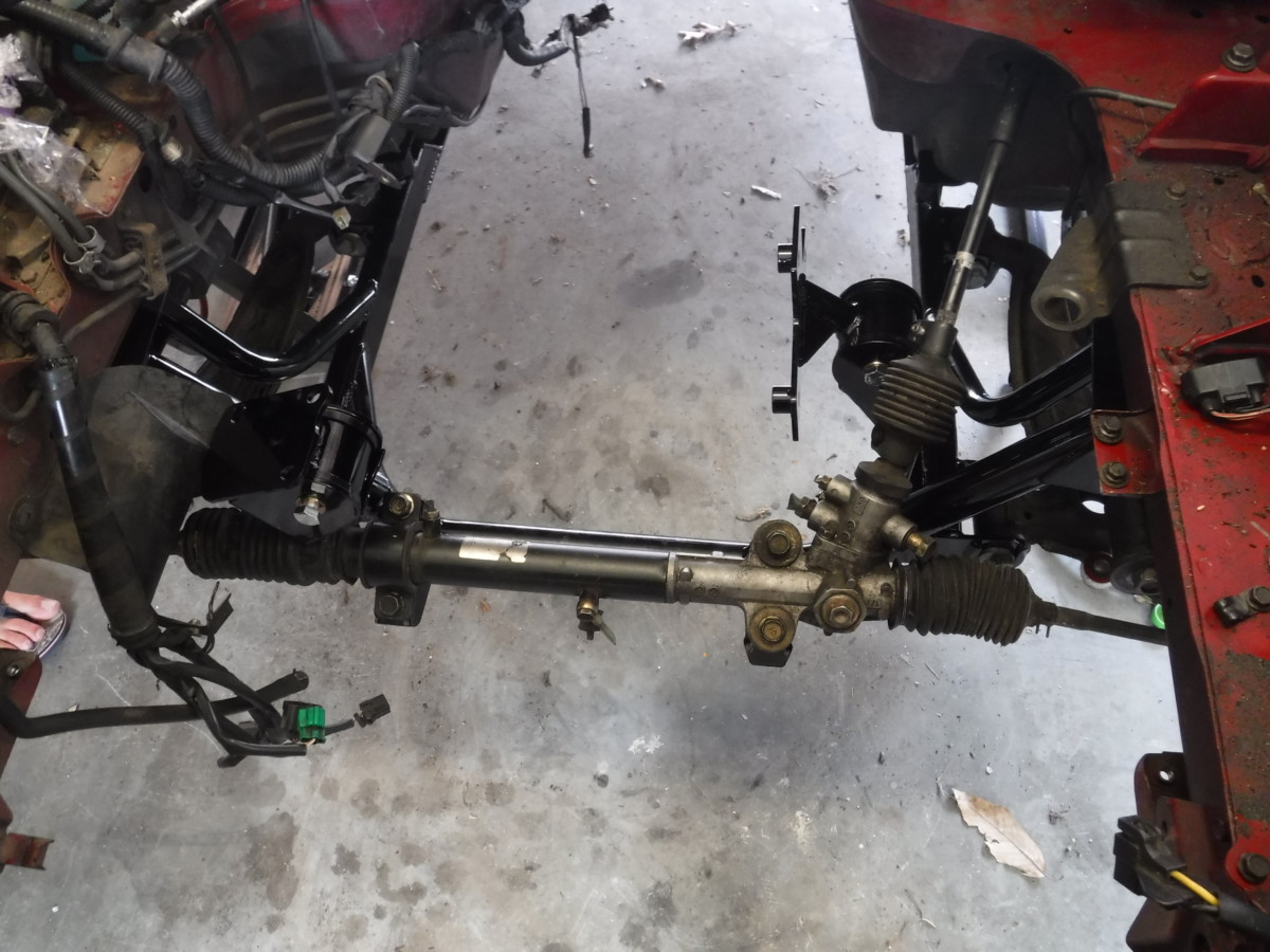
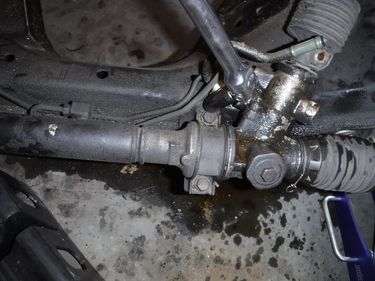
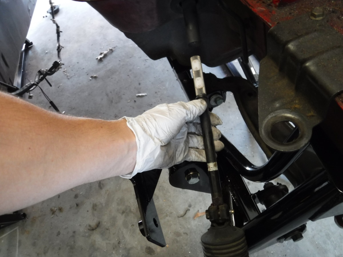
The steering rack can be installed next
There’s enough room to slide the rack onto the lower column section and reinstall the four main mounting bolts.
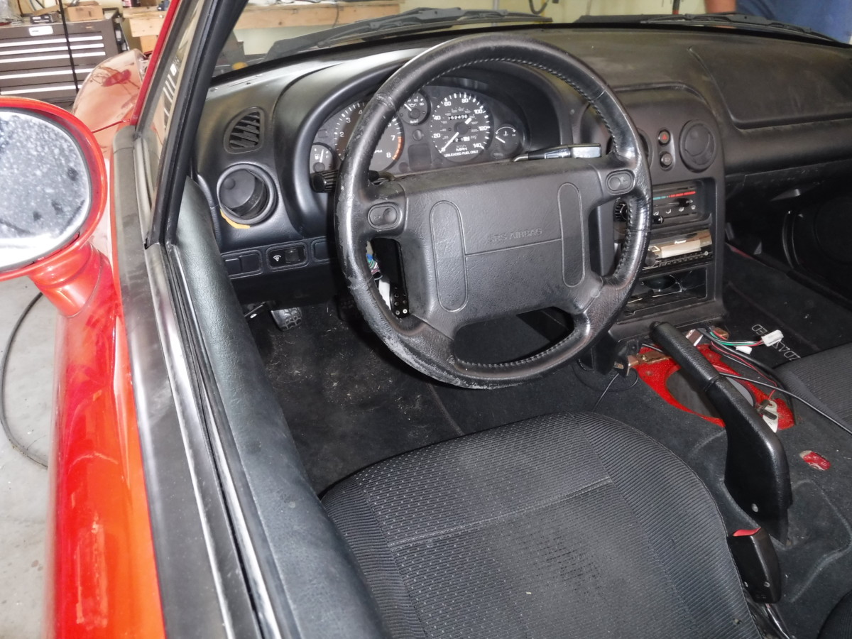
Make sure the wheel is straight
Double-check that the hubs are relatively straight when the wheel is centered
Before bolting everything permanently, make sure the steering wheel and wheel hubs are both straight or close to it. You’ll still need an alignment, of course.
Done
And here’s the rack after bolting it all together. The four main bolts pictured get 55-77 lb-ft, while the tie rod end spec is 22-31 lb-ft.
Note that the inlet ports aren’t shaved down on the rack in this picture. I screwed up and had to go back and do that later, but I would recommend doing that in the order I described.
For more instructions, see all K24 swap articles: K24 Miata Swap Main Page