Heirloom DIY Crib: Part 2
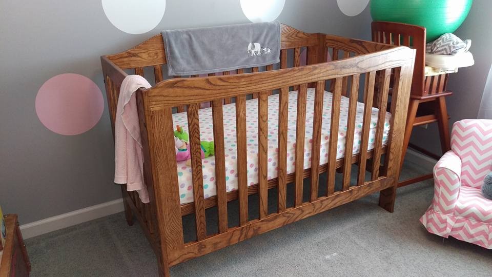
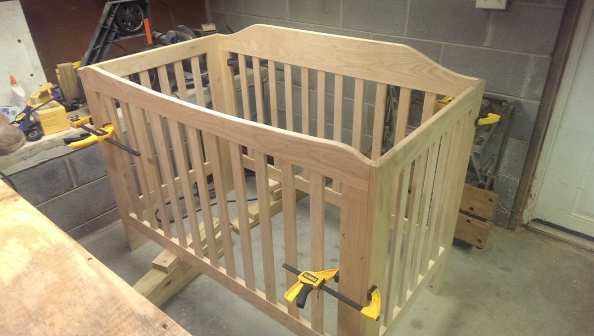
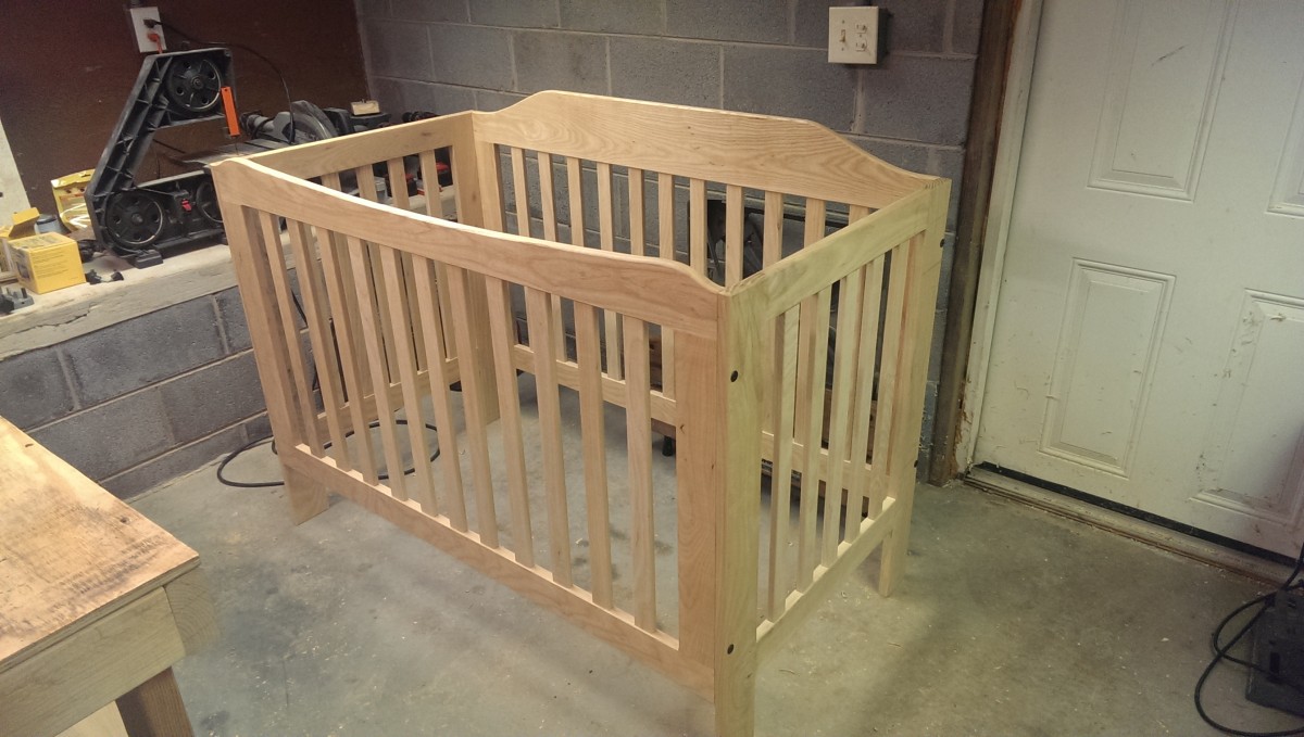
Spoiler alert: here’s what the finished crib looks like
This is a continuation of my series of articles about building a crib for my daughter. In the first part, I bought and milled some rough lumber (ash), and rough cut the structural members for the side panels and front and back panels. In the second part, I finish all four panels, including routing and installing dowels and threaded rods. In the third part, I finish the mattress support, and sand and stain.
Click here for part 1
Click here for part 3
Making a mortise template for the slats
I determined that I’d need about 32 slats. 11 for the front and back, and 5 for each side. The thought of making mortises again the way I had for the main members of the panels was not great. I decided instead to make a router template and use a template bushing in my router. Again, I wish I had had a pantorouter instead, that would be even better. If you don’t have a template bushing subbase for your router, I have a writeup on making a subbase for one out of Lexan.
The makings of a template
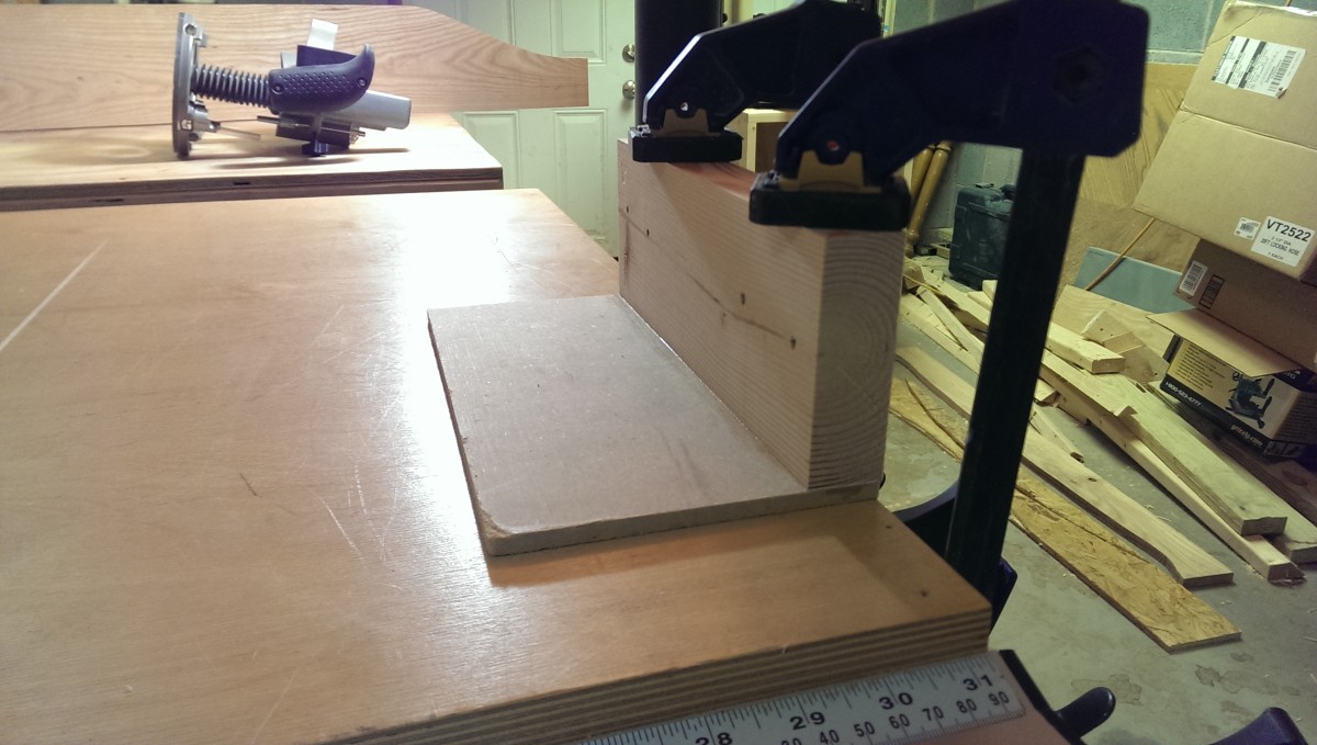
Have the flattened 2×4 proud of the template surface
The first step is to make something to use as a template. I had scrap 1/4″ MDF and 2×4 lying around, so I used that. I want to make something that I can simply clamp to a workpiece and get consistent alignment. I flattened the piece of 2×4 and glued it to the MDF, as shown, with the 2×4 intentionally a little bit proud of the MDF, as shown. The reason for doing this will become clear in a second.
Let that dry fully. Afterwards, it’s not a bad idea to sink a couple of screws through the MDF into the 2×4 for extra strength. I actually moved on to the next section while this dried, but I’ll describe the whole thing here for consistency.
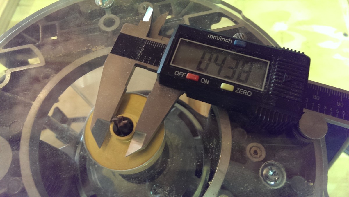
Bushing outer diameter
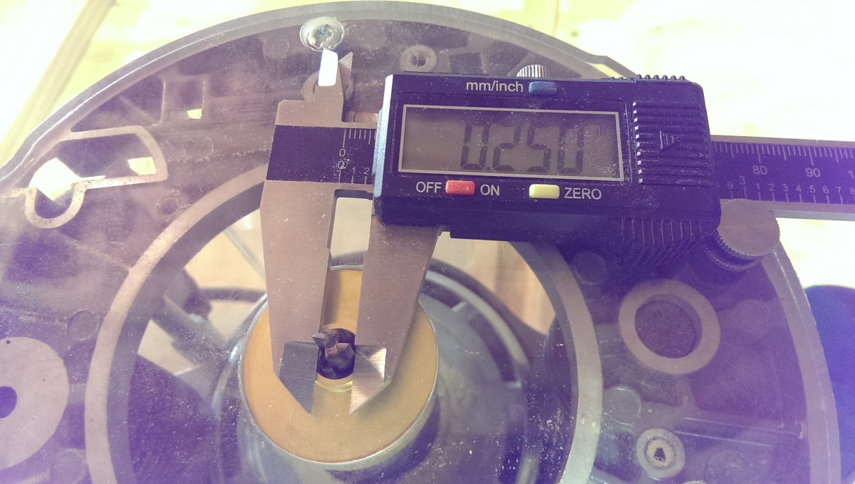
Bit diameter
To make a mortise template, the goal is to make a slot slightly wider and longer than the desired mortise, to account for the dimensions of the bushing itself. You can see the bushing mounted in the subbase in the pictures. Technically, I should use a larger bushing to allow more room for dust to come out. Unfortunately, nothing else I had had the right height, and would have gone past the 1/4″ MDF.
To plan this, I first measure the bushing and bit with calipers. They’ll have a stated size, but it may well not be accurate. Since the bushing is .438″ wide, I’ll have to use a 1/4″ or 3/8″ router bit to make the slot, moving the fence once to compensate.

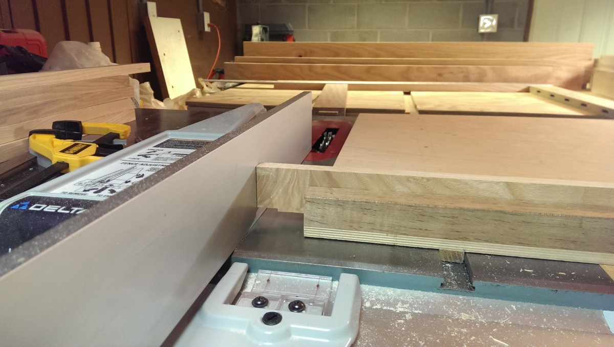
Initial setup of the router table fence
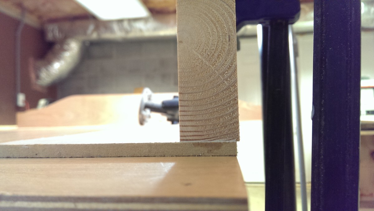
Thus begins the initial setup of the router table fence. I adjust it for one edge of the slot first. The inside edge of the plywood is going to sit on the edge of the workpiece, so I can use that as reference. The 2×4 was set proud of the MDF earlier so that the 2×4 registers against the router table fence for this step. If the MDF were proud of the 2×4, we would reference off the MDF to cut the slot, and then off the 2×4 in use, and the mortise wouldn’t come out properly.
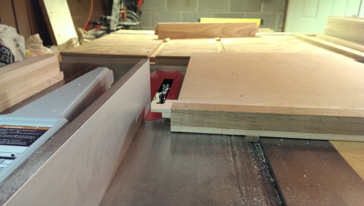
At this stage, I set up the fence to cut the far end of the slot. I know that I want the fence positioned so that the distance from the 2×4 to the far end of the template slot is half the piece to be mortised ((7/8)/2 = 7/16″) plus half the diameter of the 0.438″ bushing (.438/2 =0.219″). So I can set the fence so that the distance measured in the picture is 7/16″ + 0.219″ = 0.656″.
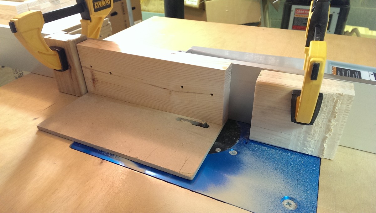
Using stop blocks to cut the slot
I can then set up some stop blocks on the fence and make the slot. The stop blocks need to account for the difference between the bushing and the bit. So if I want a 3/4″ mortise, I need to set the stop blocks to cut a 3/4″ + (2*.219″ – 2*.125″) long slot in the template, which is .938″. Since the tenons aren’t cut yet, this distance isn’t overly critical – we can make the tenons wider or narrower to compensate, provided it’s in the ballpark.
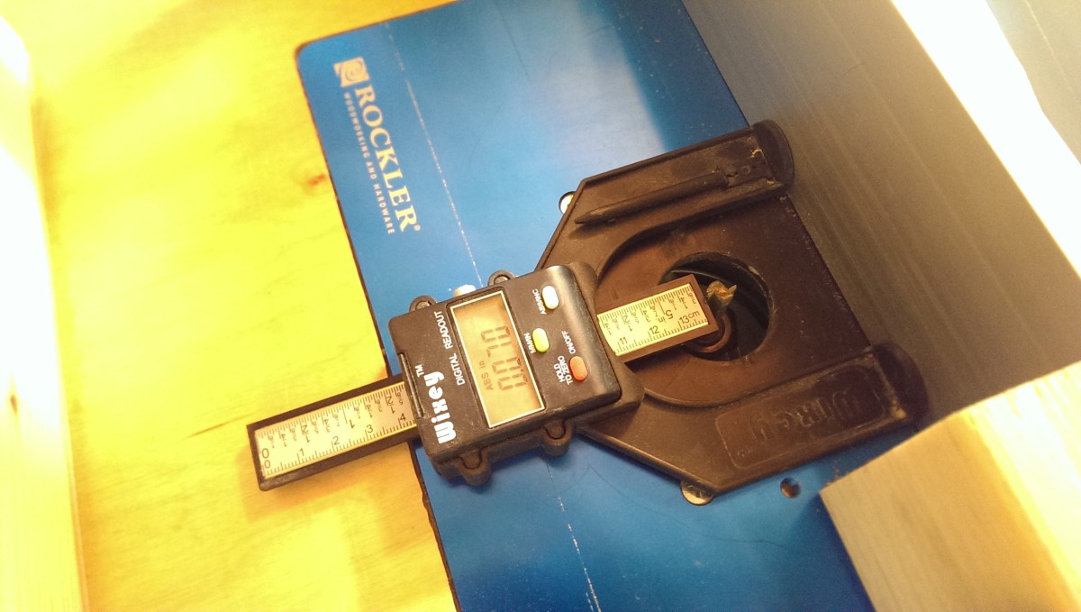
Adjusting the fence for the other half of the slot
Once the first half of the slot is cut, I need to adjust the fence to account for the other side. I ended up doing this relative to the first cut. I know I want my slot to be 0.438″ wide, the diameter of my bushing. Since I used a 3/8″ bit, I cut a .375″ slot already. So I simply need to move the fence .438″-.375″ = 0.063 inches. I don’t really want this to be super exact or else it’ll be hard to slide the bushing in the slot, so I rounded up to 0.07″ inches over to give a bit of wiggle room.
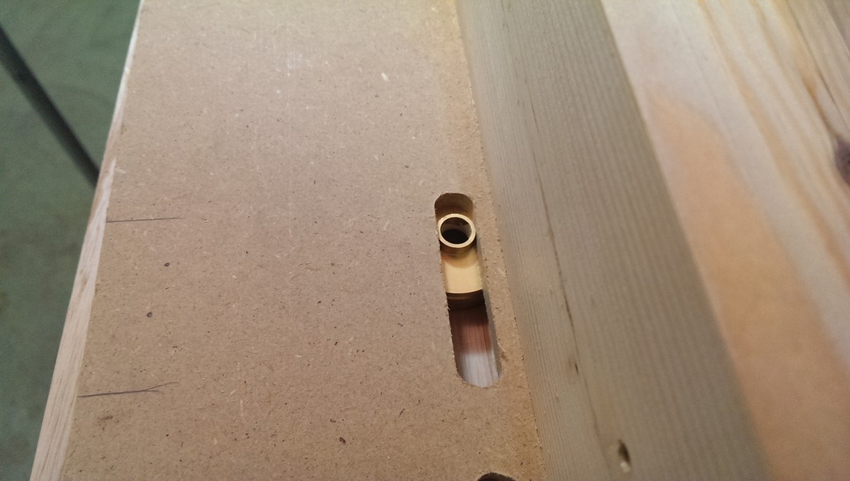
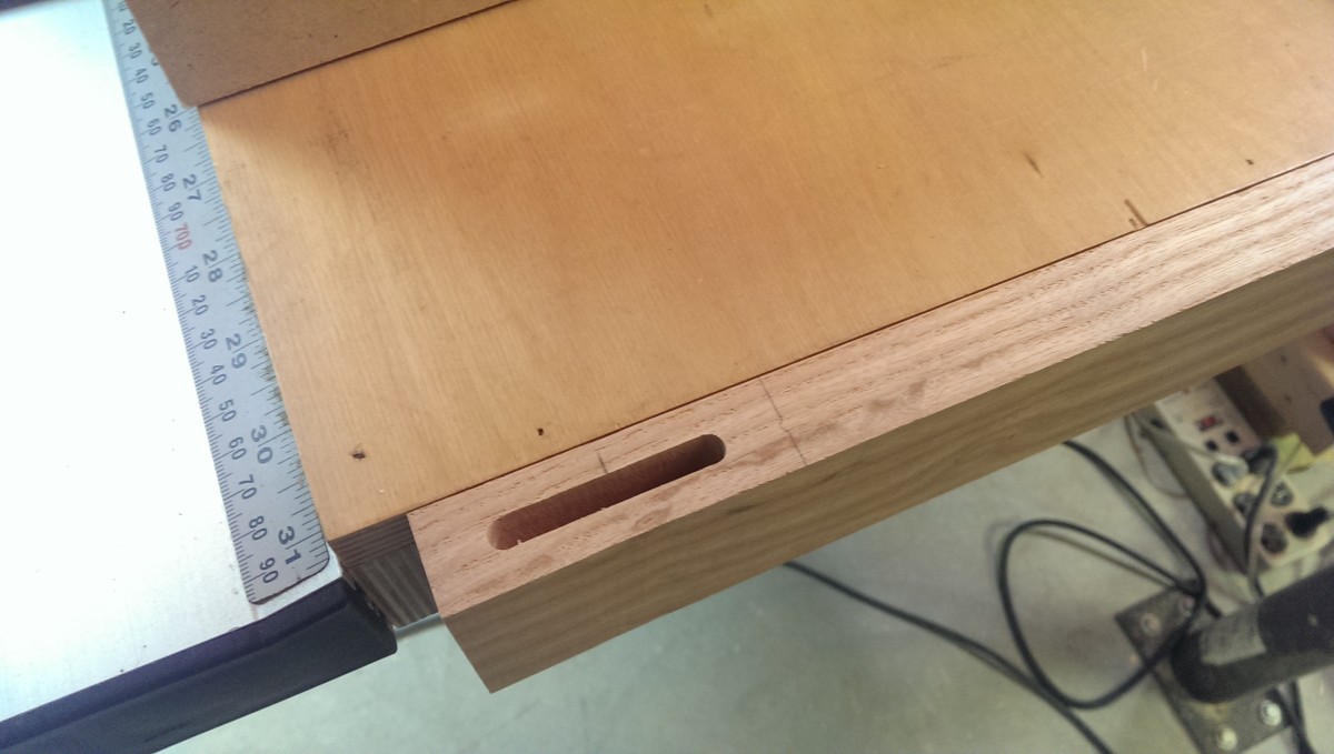
Slot is done
I made the second cut the exact same way, leaving the stop blocks in place. Once done, I confirmed the bushing slid nicely in the template without much play.
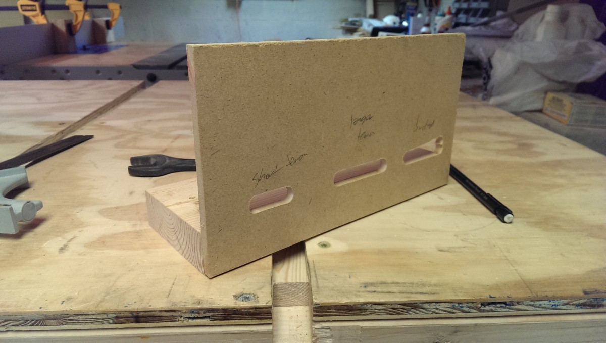
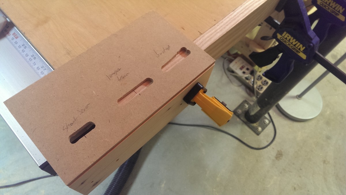
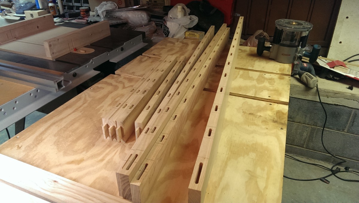
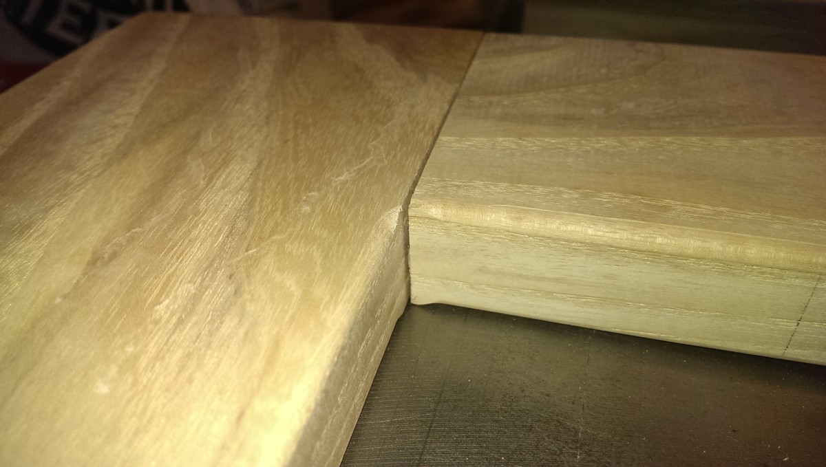
Final template, one long, one short, and one I screwed up
I was able to make several mortise templates on one piece of wood, which saved time waiting for glue ups, etc. I did have the fence set wrong in one case, and that part of the template was unfortunately ruined. In this image, the short mortise template is for the slats. The longer mortise template is for attaching the 4 main vertical and horizontal pieces for the front and back panels. In part 1, I had done this using an edge guide, but after the issues I had with that, I chose to use templates for everything.
Making Slats
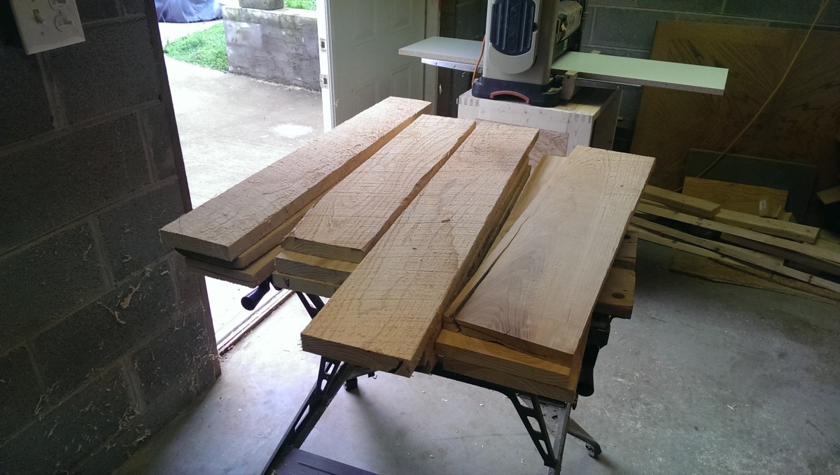
Rough lumber for the slats
I actually began doing this while the glue on the mortise template was drying earlier, then went back and finished the templates. In any case, to make the slats, I did as before, rough cutting the boards to length and milling on the jointer and planer.
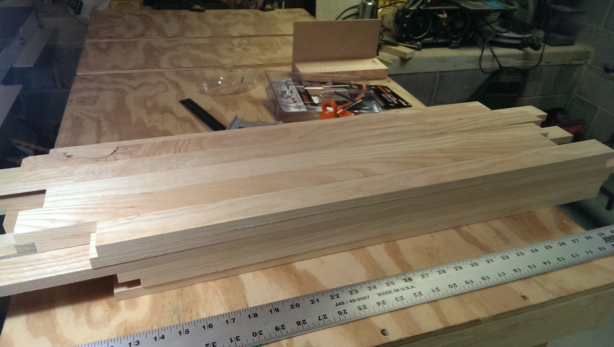
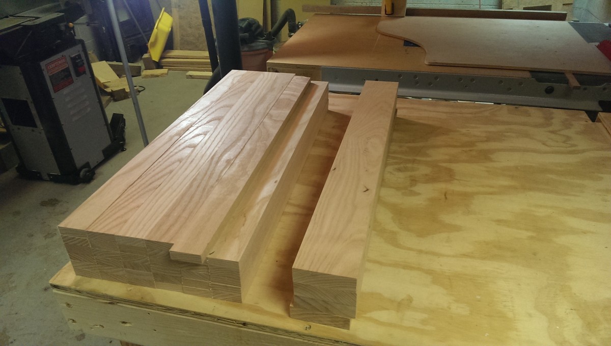
Slats after milling
I intentionally chose some of the thinner pieces of my stock, because I made the slats about 1/8″-1/4″ thinner than the main members they connect to. Doing so is both visually appealing and also makes mortise and tenon placement less critical – you don’t notice if a slat is a few hundredths off-center if it is thinner than the piece it connects to. If I made them the same thickness, you could see or feel if they were off.
If I had a good bandsaw at this point, I would have cut them down on it to save wear on the planer and have some veneer I could save. Unfortunately, I didn’t.
Another mistake I made here was to do final milling of wide boards that I ripped down. This resulted in some warping as internal stress released. I ended up running them back over the jointer and planer, thinning them even further. Some ended up being too warped to use. Additionally, jointing such a thin piece is pretty tricky, and I can’t say I enjoyed doing it. I’m not sure how I would handle this if I did it again.
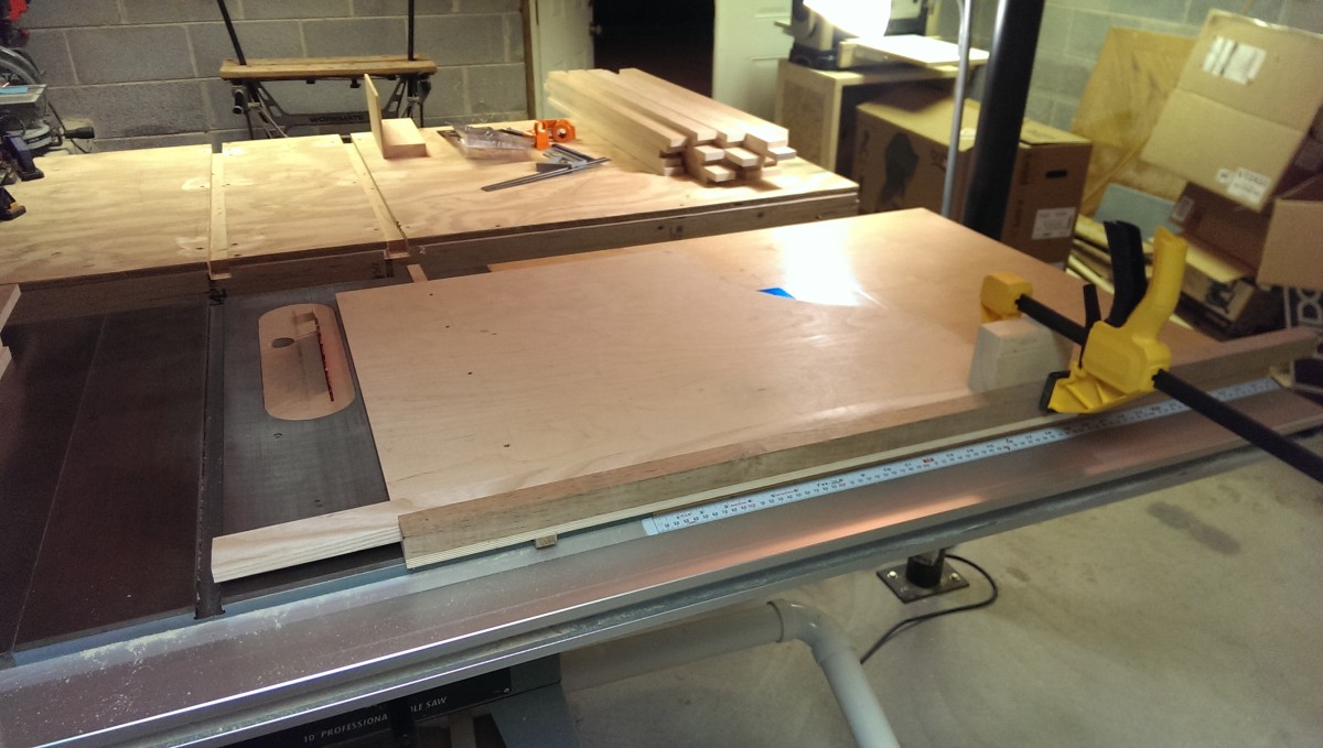
Using a stop block and sled to cross cut the slats
I then proceeded as before, using my table saw sled and a stop block to lop the slats down to appropriate width.
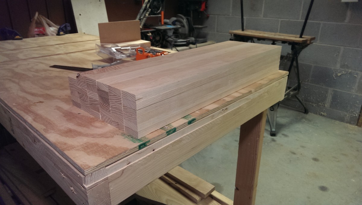
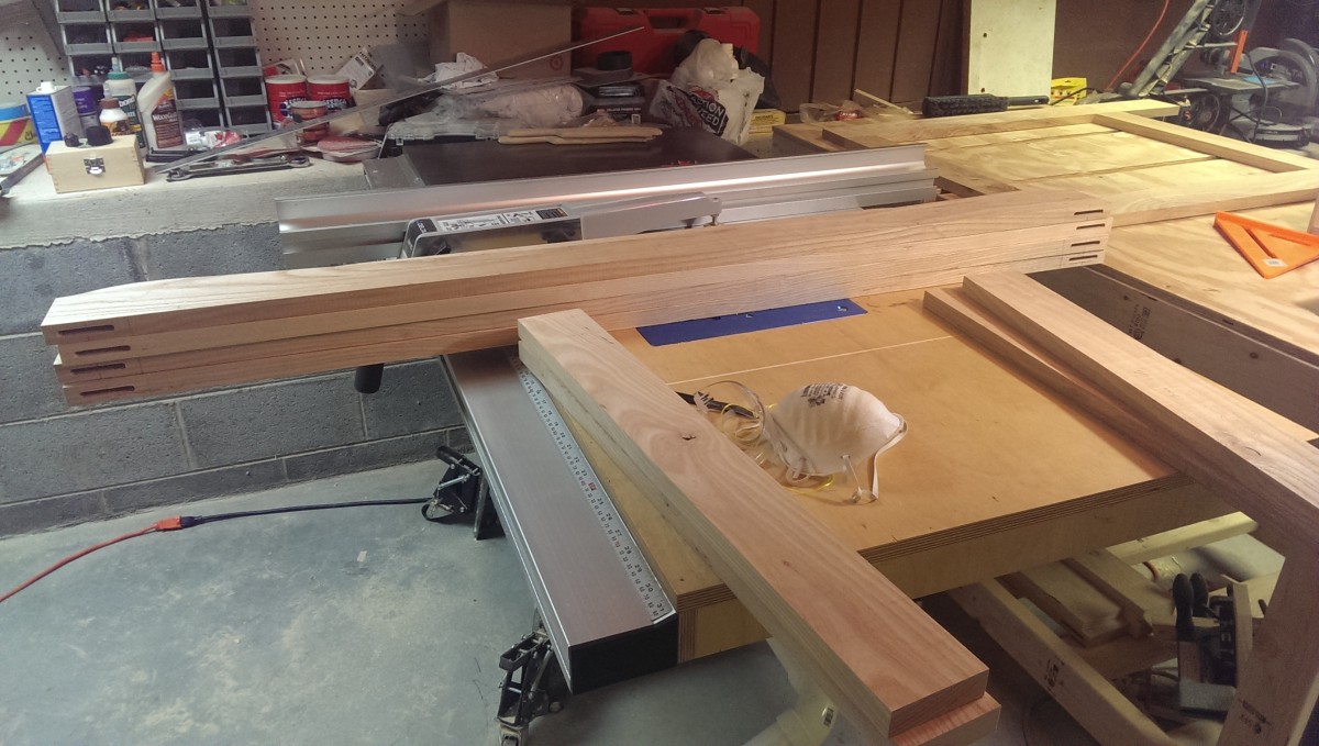
Slats are ready for tenoning
Also cut the verticals for the front and back panels to the same length as the slats
Once they were all cut down, the slats were ready for tenoning. At this stage, I also cut the verticals for the front and back panels. On the side panels, the vertical members run all the way down to the ground, and the horizontals sit between them. In the case of the front and back panel, the horizontal members run all the way to the end of the panel, and the verticals sit between them. I did this because with the side panels, the vertical members are holding the weight of the crib. With the front and back panels having decorative upper members, it was much easier to cut the curves on a single piece of wood than if the vertical members ran all the way to the top of the crib.
Mortising for the slats: Using the mortise template
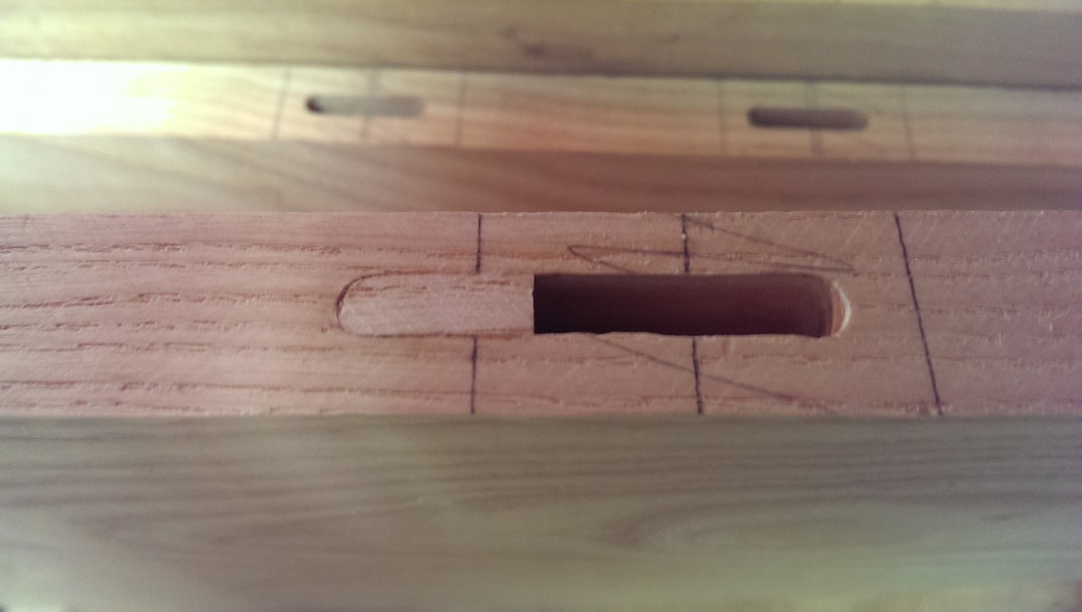
Cutting the longer mortise for the main member on the far edge of the board
Nice, clean, consistent mortise
Mortises cut for the main members
I first started by using my wider mortise template to cut the mortises for the main members. The templates let me place them very consistently. I marked the center of each template in pencil, so that I could use that as an easy reference.
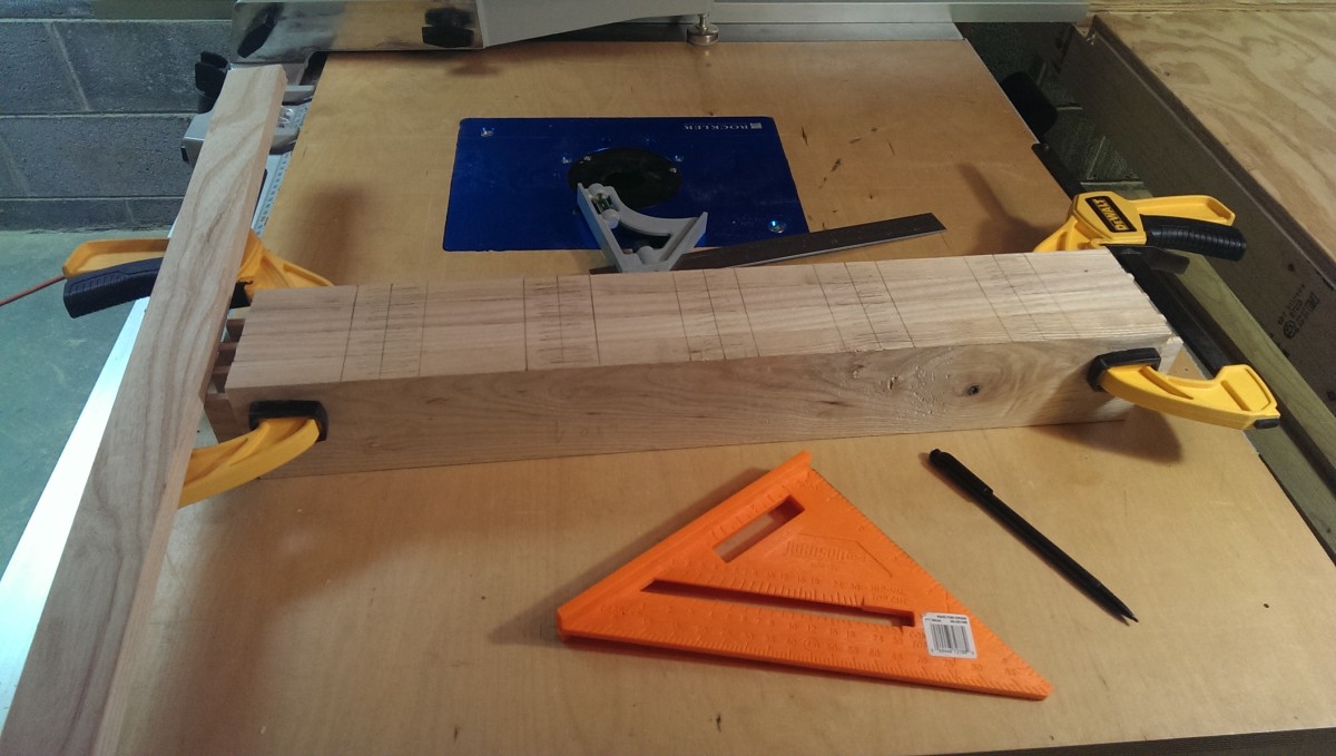
Marking slat locations
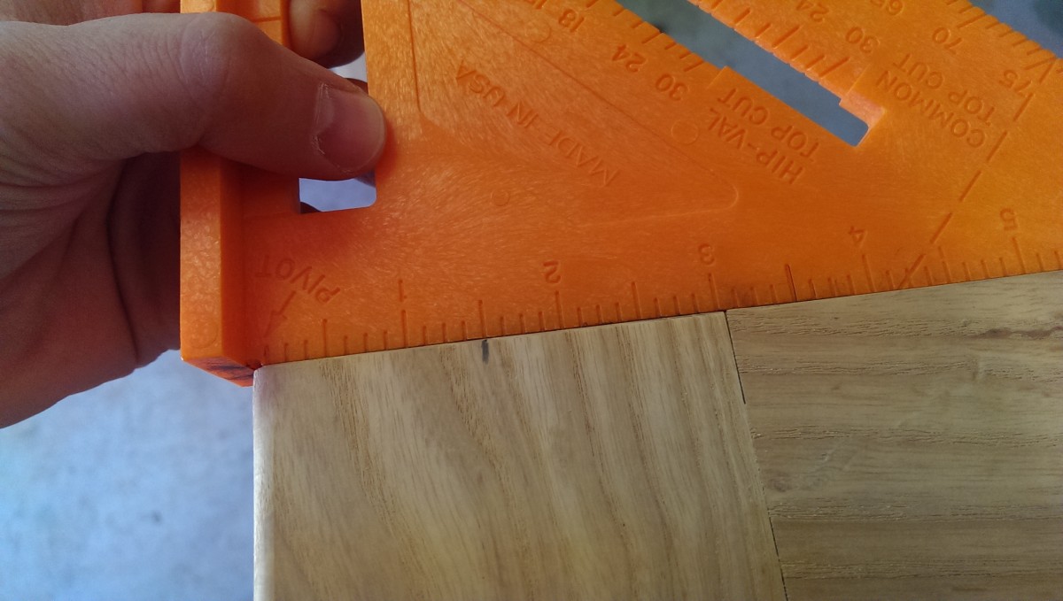
These are the horizontals for the side panels, which need 5 slats. I clamped them all together, straight, and used a speed square to draw lines where I wanted the mortise centers to go. I made sure the final slats would be no more than 2 3/8″ apart at this point. I used pencil to fill in where material would be cut, to prevent myself from mortising on the wrong line.
This took forever
I then used the same technique as before, with the short template, to route out all of these mortises. There were 64 mortises in total. I’m really glad I didn’t try to do this with the edge guide! The mortises came out very consistently.
I did screw up once
I recommend filling in the area to be mortised so you don’t screw up like I did. When moving the template along the lines, it was sometimes hard to spot which line was the center vs outsides. In one case, I mortised with the template in the wrong place. I ended up rounding over a piece of scrap and then cutting it down to fit, gluing it in place. As repairs go, it wasn’t too bad.
I’ll also note here that some people accomplish this sort of thing by cutting one long dado in the piece of wood. I could have done this much more quickly, but I didn’t want to for two reasons. One is that it makes the glue-up trickier on a project like this, where slat spacing is critical. If your slats fit into one giant dado, they can be placed anywhere along it, and if you need them to be no more than 2 3/8″ apart, this is easy to screw up in a way that is very hard to fix.
Secondly, though, I simply wanted to do the project “right”. A long dado is perfectly acceptable, and I probably would have done this if I were selling these commercially and needed to crank them out. I like to think, however, that another woodworking looking at the completed project would notice the use of individual mortises as a sign of the care that went into this project.
Tenoning the slats: Using a dado stack
Set up for shoulders
After my experience with the tenoning jig, I decided to simply use my dado stack for the mortises. I simply used my crosscut sled, dado stack, and fence. The Unifence I have can be set short so it doesn’t touch the blade or cause a safety concern. On a Biesemeyer-style fence, I would have clamped a stop block. Either way, I use the fence to set the tenon depth. The height of the dado blade determines how wide and thick the tenon is.
Cutting the cheeks
I probably should have taken more pictures, but there are tutorials all over the internet. The basic idea is to take a pass just doing the tip of the tenon, and then do a second pass all the way against the fence. You’ll get a score mark on the tenon, which nobody will see, but otherwise this works quite well. Until I build a pantorouter, I intend to do my tenons this way.

Done
And with that, you can double-check to make sure everything works. I intentionally made the slat tenons a little looser than I normally would, so that they don’t cause issues during glue-up later. The larger mortise and tenons provide most of the structural support anyway.
Routing and glue-up
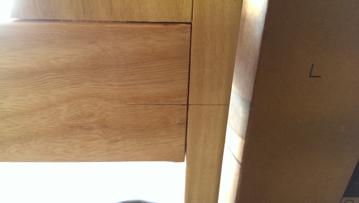
At this point, I was ready to put the finishing touches on these panels and glue them up. Since it is mission style, I didn’t want the crib to be overly rounded. I ended up using an 1/8″ roundover bit in most cases, except along the top of the crib, where I used 1/4″. I also used a little 1/16″ roundover bit to simply smooth corners on edges that were going to be bolted together flush and on the bottom of the legs.
Stopped short on the edges
One thing to note is that I stopped short intentionally where I knew wood would come to an inside corner, as pictured. If I kept going on the piece on the left, I would have a very weird edge once it was glued together. Since the slats would be in the way of my router after glue up, I simply rounded over like this for now. Then later, when it was all glued together, I use a brass-bearing bit and sometimes a file to knock out these inside corners.
At this stage, I also sanded the mortised surface of the major members and the entirety of all the slats prior to glue-up. I am sanding everything to 150 grit, so that it takes the stain properly later on. Even though I still had to hit them again with sandpaper later, this at least let me sand while it was still easy to access. Once installed, the sides of the slats and the mortised surfaces in particular are very difficult to get to.
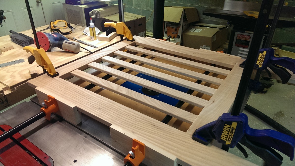
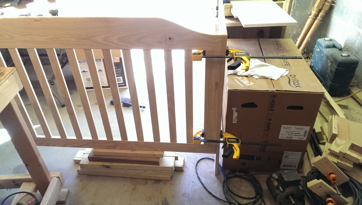
Gluing up a side panel
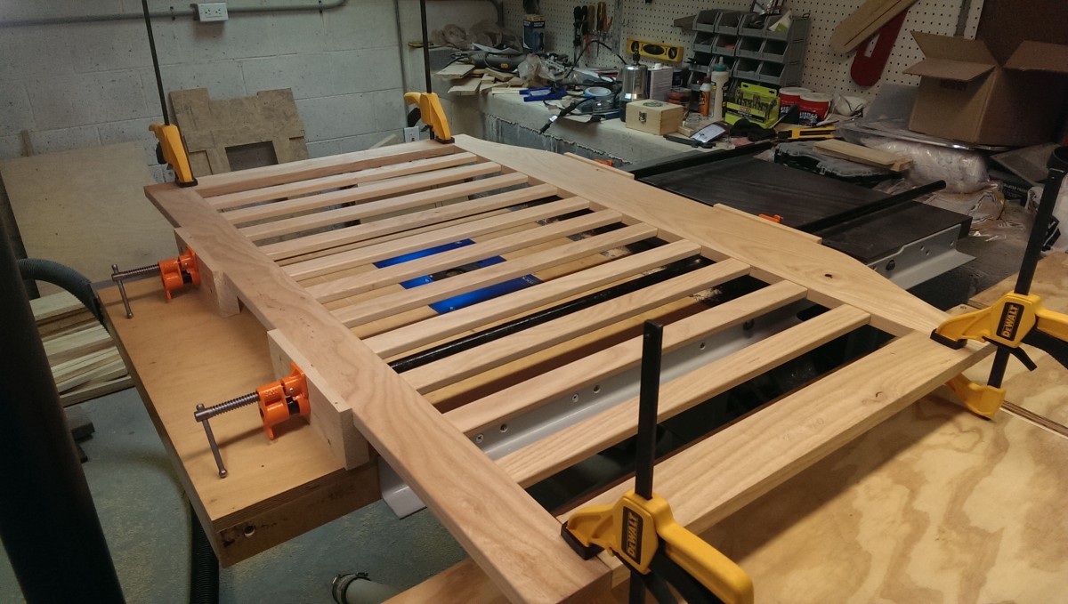
Gluing up the back panel
The glue-up was pretty straightforward. First, I glued the entire thing up as quickly as possible, which is a bit of a panic exercise. Then, I used two pipe clamps, which are really a poor man’s panel clamp, to hold the whole thing together. I have cauls made from 2×4 to hold the pieces level. I then put clamps on all of the edges that I want to ensure are flat and even. Finally, I tighten everything up and use sawdust to wipe away squeeze out.
In general, this worked fairly well. I glued everything up on my table saw because it’s the only surface in my shop I trust to be flat. I really need to make a real workbench.
Doweling the panels
Dowel rod sucks, buy individual dowels
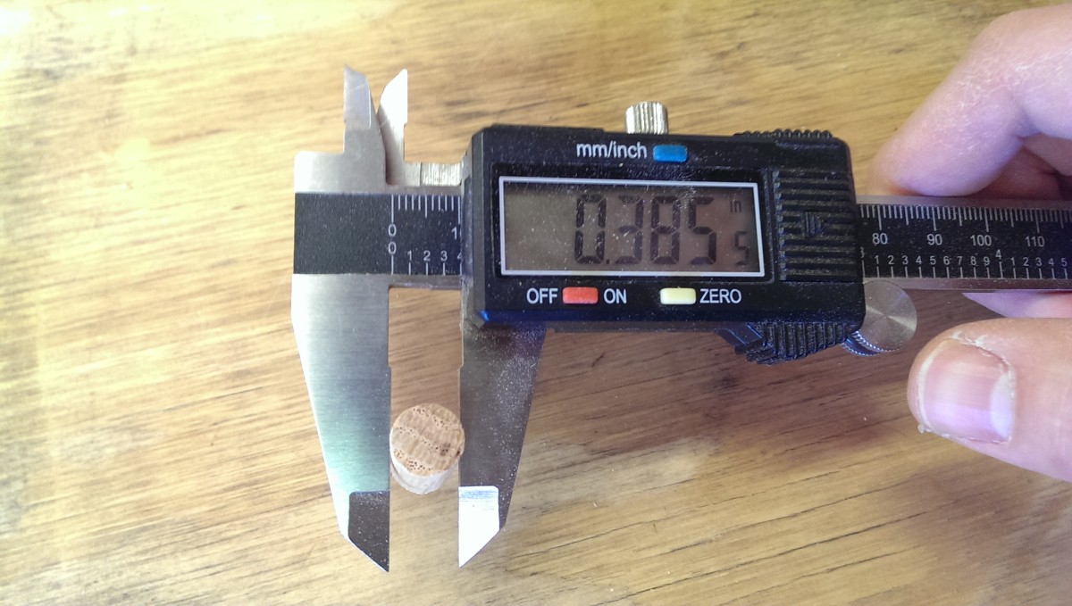
Yeah right on the 3/8″ – .010″ is a lot!
As I said, I have 2 bolts per corner plus 4 unglued dowels holding the panels together. The dowels provide extra strength, particularly against racking, as well as alignment. I first started out with dowel rod, which I highly recommend AGAINST. This stuff is a lie. The “3/8″ dowel I bought was not 3/8″ and was not even consistently round. The above one was .01″ over, but even that wasn’t consistent. The result was that I couldn’t fit it into a 3/8” hole, making it worthless. Going the next size up in drill bits would have way too much play.

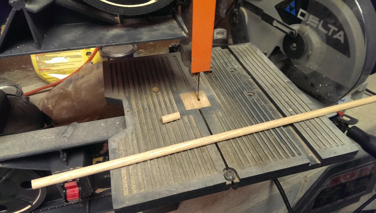
Buy these instead of dowel rod or make your own dowel rod
Instead, I used a pack of dowel pins. They cost a little bit more, but were consistently 3/8″. I’ve also seen Matthias Wandel and others make their own dowel rod by rounding over all 4 sides of a piece of wood, and then run it through a jig using a drill. This looked more complicated than I wanted to deal with; I was happy to just pay the $4 or whatever for 35 of these.
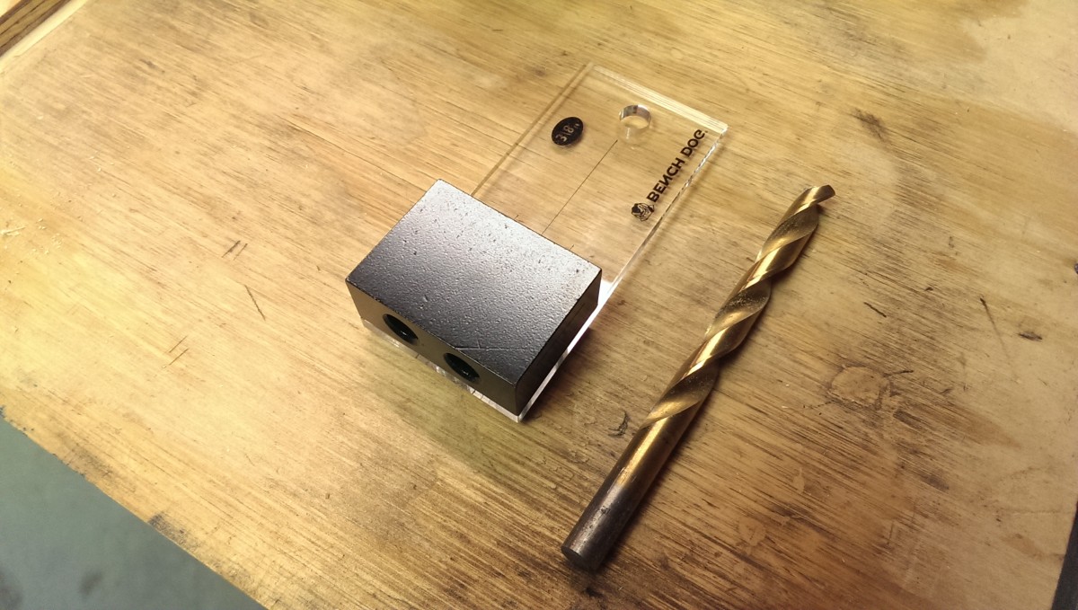
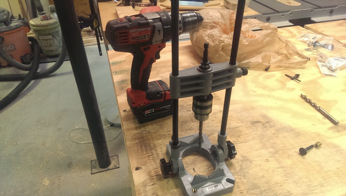
Jig and 3/8″ drill bit
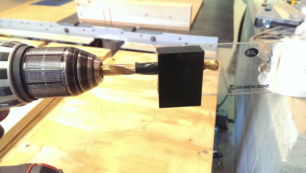
“Depth Stop”
I ended up using a little bench dog 3/8″ doweling jig. This actually worked much better than I had anticipated. One thing I like about it is that the body of the jig is steel, so it doesn’t appear to wear all that much. I used some tape as a depth stop, although I also went back with the drill press where I could.
Marked the approximate center
I marked the approximate center of one side of the joint to be doweled. This doesn’t have to be particularly accurate.
Clamped up
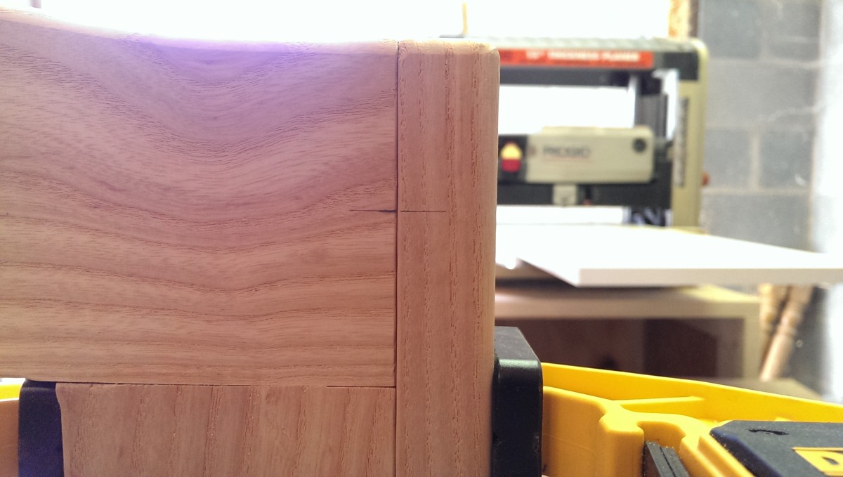
Top mark
Bottom mark
It doesn’t have to be all that well centered because of the next step. I clamped each corner up and used my speed square to mark a consistent line across the joint. I can now use my bench dog jig’s center line to drill the holes, and be assured it will end up consistently spaced. Even if the line is a bit off-center, it doesn’t matter as long as it’s the same on both pieces.
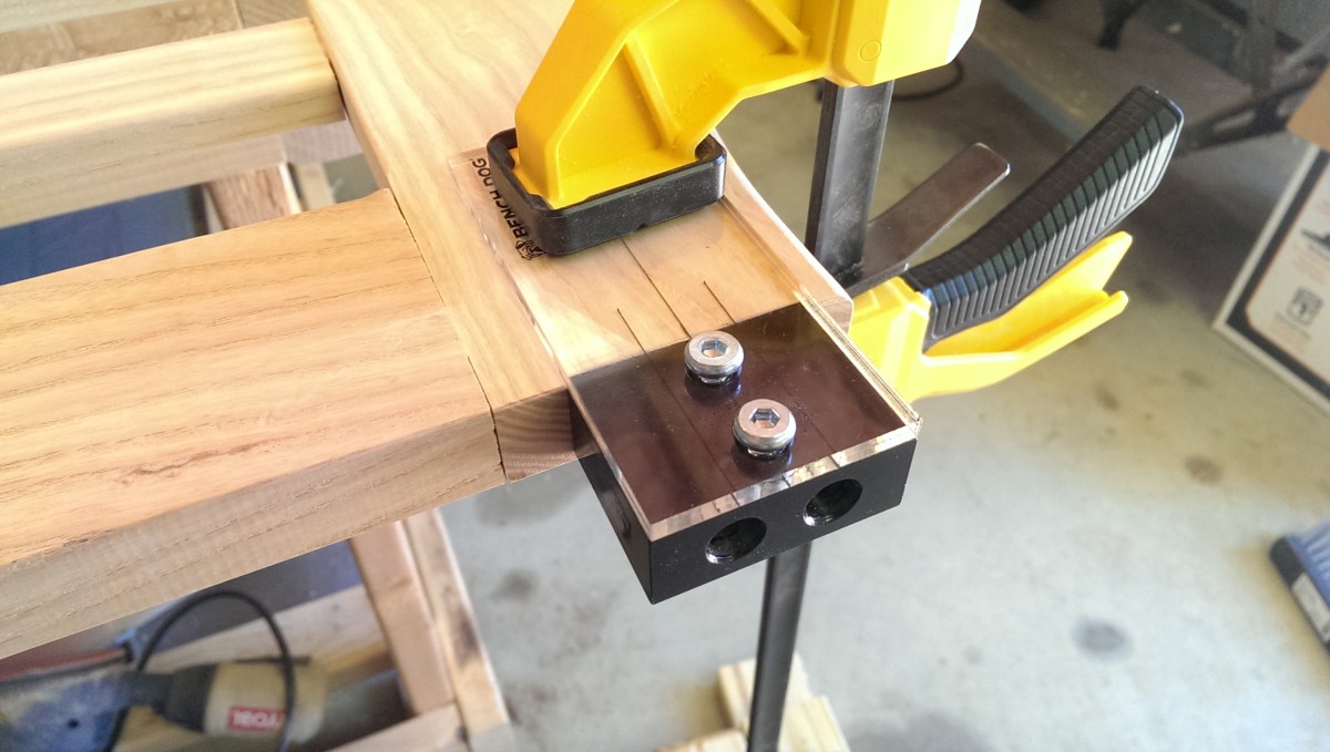
Clamping the center line
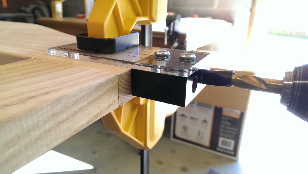
Drilling
The jig actually made it very easy to clamp and drill. I tried my best to keep the hole straight, which the jig helped with as well. For the holes into the side of the workpiece like this, I wasn’t as concerned about accidentally drilling too deep.
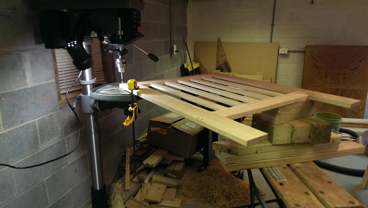
The drill press let me get consistent depth where it mattered
However, I was concerned about breaking through the holes on the side panels, since I only had 7/8″ of material to work with. As a result, I ended up rigging up my drill press to drill these. First, I did a 3/8″ shallow hole using the jig for placement. Then, I used a 3/8″ forstner bit in the drill press as shown to get the right depth hole without breaking through.
Test fit looks good
I was then able to do a test fit with the dowels installed. So far so good!
Threaded inserts for bolts
Right-angle jig
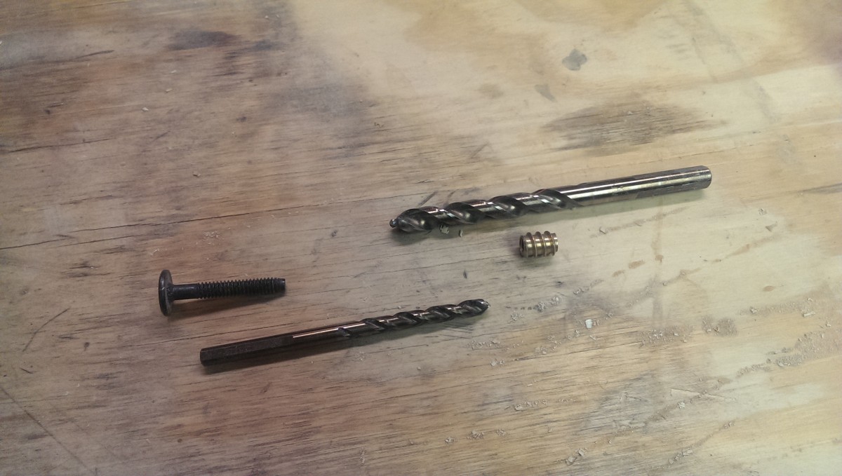
The furniture bolt, matching threaded insert, and drill bits for each
In addition to the 4 dowels per corner, I also added 2 bolts. These actually hold the sides to the front and back in a way that is strong but removable. Unfortunately, there was really no way to use the drill press to do these holes, so I had to use a right angle drill adapter instead. These little adapter jigs have a lot of play, but they’re better than drilling free hand and do have a depth stop.
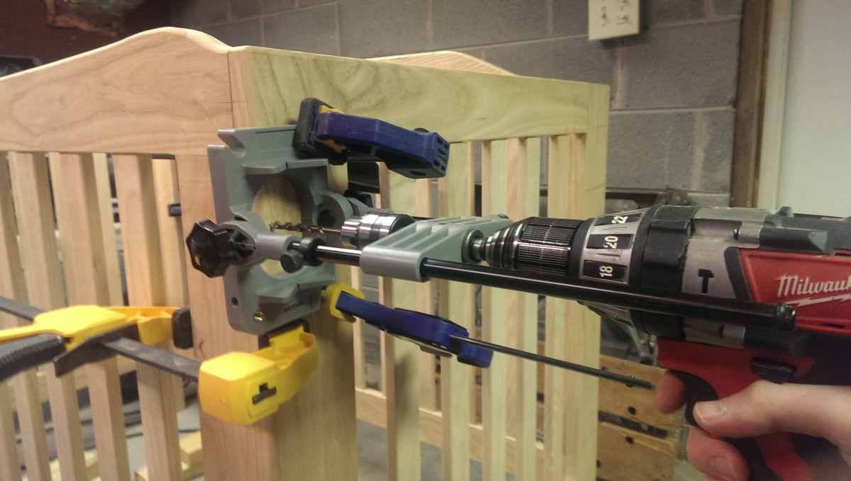
Drilling through-hole as wide as bolt threads
I used the jig as shown to drill a straight hole through the side and into the front panel. The bit I used was the same diameter as the outside of the threads on the bolt. I wanted the bolt to easily slide through this hole. I made two of these holes per corner, one at the top, and one at the bottom. I’ll note here that I’m placing the bolts so that they go into the cross grain on the front panel. This is important, because threaded inserts hold better in cross grain than in end grain.
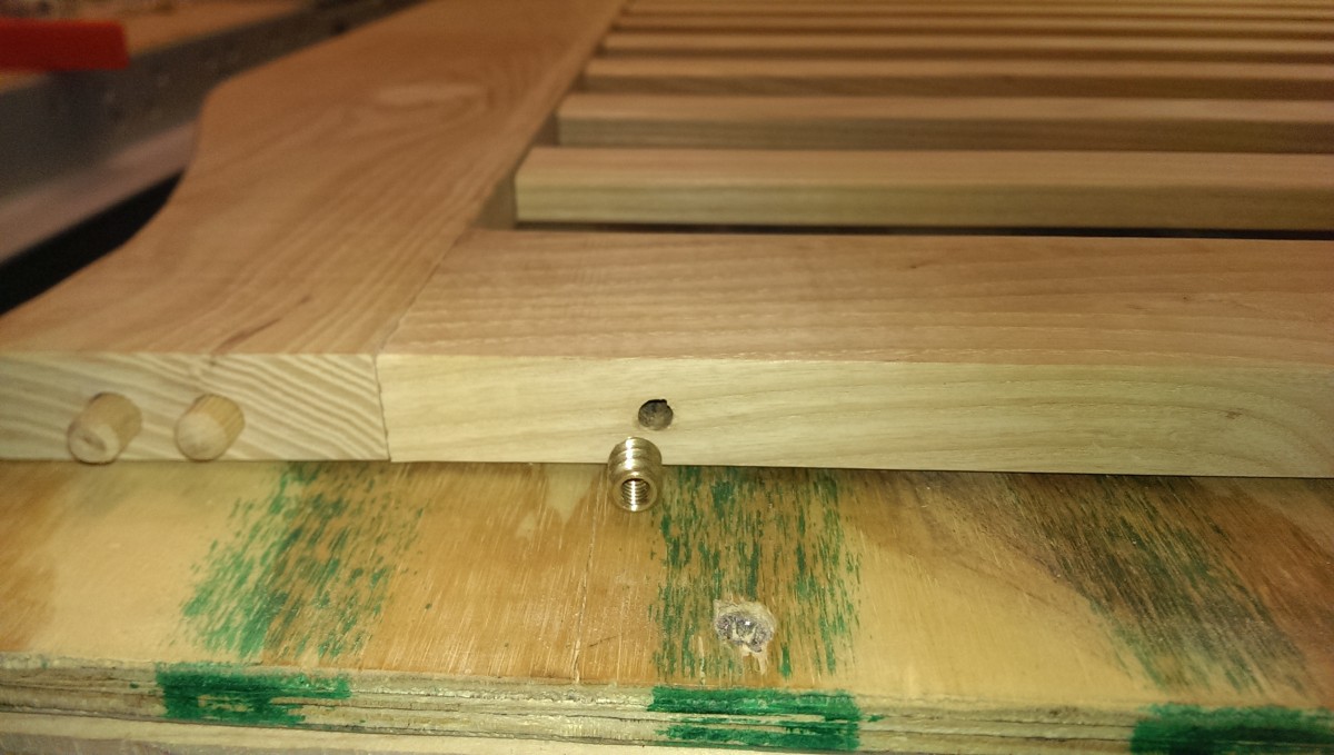
Threaded insert
I’m now ready to install a threaded insert in each hole. The threaded insert requires the bolt hole be expanded a bit.

Expanding the hole
I used the right-angle jig again to enlarge these holes. The target diameter is specified by the threaded insert manufacturer. In general, the proper size is larger than the body of the threaded insert, but smaller than the outside of the threads. The larger the hole, the easier it is to drive the insert in and the less tear-out you’ll get, but the less well it will hold.
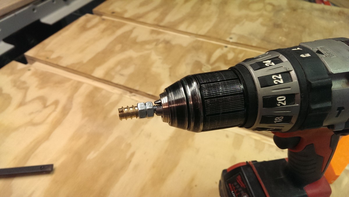
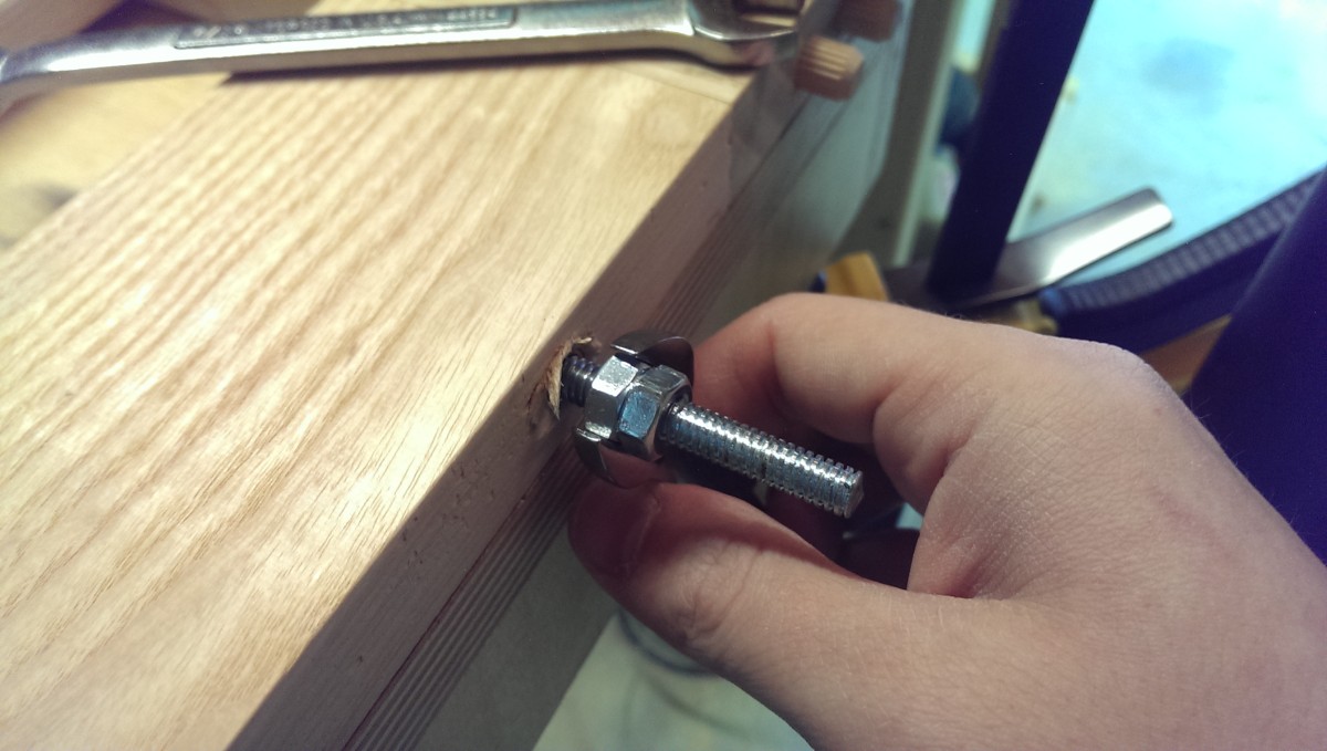
Install the insert using some threaded rod, two nuts, and the insert itself
The installation is done by threading the insert onto some threaded rod or a bolt with the head cut off. Two nuts are placed behind it. The entire assembly can be placed in a drill. Ideally, this would be a drill press, but I can’t get the piece up to my drill press.
Start the insert with the drill
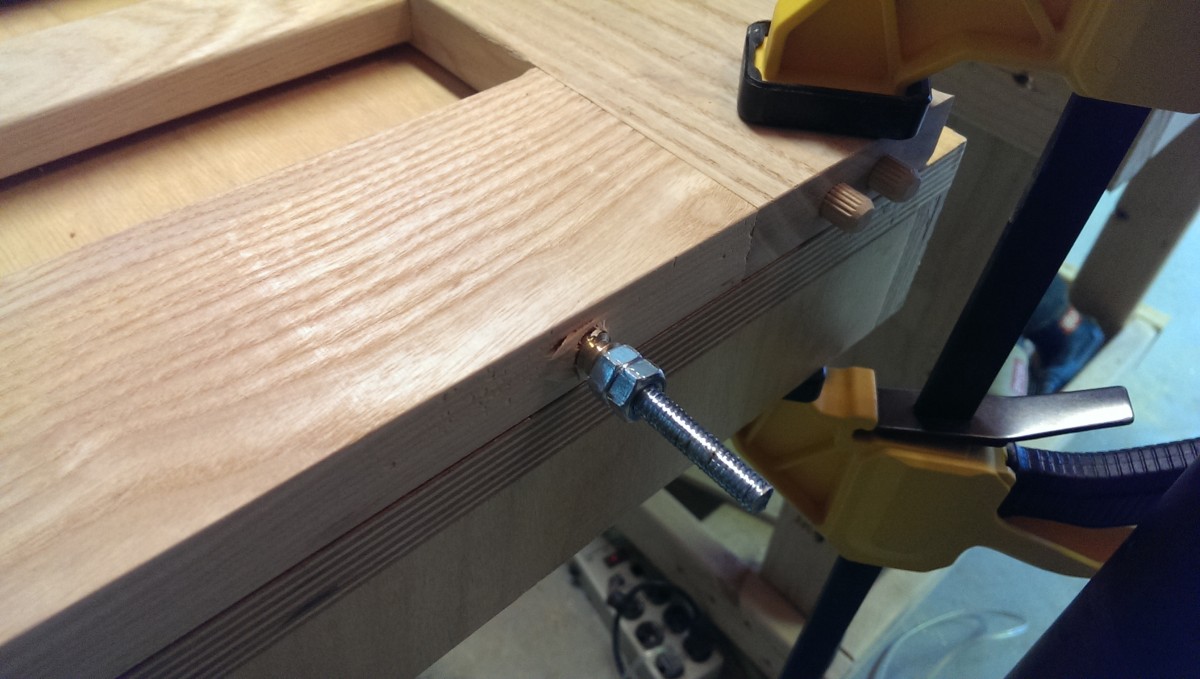
Use a wrench on the second nut to drive it in
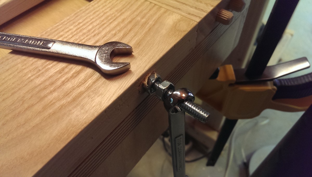
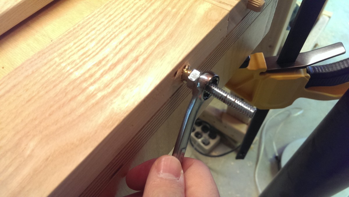
Use two wrenches to break the second nut loose
Back out the first nut until it hits the second, then keep unscrewing with a wrench to remove
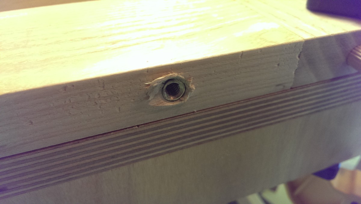
Finished, just a little tearout
I followed Ronald Walters’ procedure for this. Essentially, you start screwing the insert in with the drill. Then, you use a wrench on the outer nut to drive it flush or a little deeper than flush. You then use one wrench on each nut to break the outer nut loose. Unscrew the outer nut a few turns. Then, unscrew the inner nut until it hits the outer nut. use a wrench on the inner nut to unscrew the entire assembly, minus the threaded insert. You’re done.
As I said, when done on a drill press, you’ll get better results with less tear out, but I wouldn’t get this work piece to my drill press. I could have possibly done this before glue up, but I would be concerned it wouldn’t align correctly afterwards. Doing it this way ensures everything comes together properly.
And that’s it for part 2
And that’s it for part 2. Continue on to part 3 to see the final product.